
Perry's report of 15 Vp-p across a 50 ohm load resistor definitely got my attention. I've tested the efficiency of various Part 15 AM experimental circuits for a number of years, and I've approached, but never actually quite reached, 5 V p-p; not even when operating in a switched mode.
By the way, 100% efficiency would be indicated by about 6.3 Vp-p.
It is now apparent that any future claims of actual measurements of transmitter output power will be challenged.
"It is now apparent that any future claims of actual measurements of transmitter output power will be challenged."
Obviously. Anyone with the proper skills and proper equipment to make proper measurements would know right off of a skewed set of proclaimed measurements...be it from a test bench or simulations or real world.
Knowledge is knowing the difference between right and BS.
RFB
Perry, was there a DC component to the modulated signal you measured? I ask because I have seen such a waveform before and it was caused by a shorted output coupling capacitor. I spent a lot of wasted time looking in the wrong place (the modulator circuit) for the problem.
Neil
"Perry, was there a DC component to the modulated signal you measured? "
I don't think so. The waveform looked the same whether I switched the scope to AC or DC.
"Perry, was there a DC component to the modulated signal you measured? "
I don't think so. The waveform looked the same whether I switched the scope to AC or DC.
I'll check again though when I get a chance.
You won't measure any DC shifting that may be happening from an RF output, not unless you make a DC connection to the finals where they join.
At the RF output jack, you will only see an AC signal there, and if it has any DC shifting taking place, that will only show as a lop sided modulated RF envelope.
To see any DC shifting, you would need to connect directly to those finals to see the DC shift itself.
RFB
I'm gonna need a little more confidence in my abilities as a technician before I rip open the Talking House and start fiddling with it. Especially with a flaky scope and no schematic!
Still wondering about the weird modulation envelope? But the TH sounds reasonably good although it seems undermodulated compared with the other one. When I turn my car radio up all the way, it isn't very loud. The other TH was much louder.
Quoting RFB, "To see any DC shifting, you would need to connect directly to those finals to see the DC shift itself. ", a shorted coupling capacitor does just this.
Perry, it is common that a transmitter signal will sound just fine on a receiver despite a distorted waveform. For example, the situation I mentioned with the shorted output cap. didn't affect the signal since the DC wasn't radiated. Also, ponder a signal rich in harmonics. The receiver only "hears" the part of the ensemble that it is tuned to receive. A listening test can fail to disclose a lot of problems.
Though you may not have the best scope available to you I find it hard to accept that a voltage measurement error would be of the magnitude you reported. Your measurements may not be that far from the truth.
Neil
I'm going to use the same scope to measure the output of my friends two AM part 15 transmitters. He has a Tube AM Transmitter and an Stran 3000.
That is a good idea and here is about what to expect. Keep in mind that the AMT3000 is designed to drive a load with a series inductance so it will tune properly. A 50 ohm resistor will not allow the transmitter to tune properly however you will get a voltage reading.
For comparison, I measured the voltage across a 50 ohm load connected to an AMT3000 with no attempt to tune and the voltage was 250 mV RMS. The internal inductors were shorted via the dip switches. This was with R18 in the circuit and if your friend's unit has been modified for an external coil loaded antenna this may not be connected and the voltage you measure will differ from mine but this gives you a ballpark to expect.
No conclusions about the output power of the AMT3000 can be drawn from this because for this test the transmitter output was not tuned nor did it have the proper load for which it was designed.
Neil
Link below is to a section of the TH transmitter schematic taken from the patent PDF.
Let's start at the output jack (96). Leading to the left is C326, a 10 nanofarad cap, leading to a switch SU100, which selects internal ATU and external ATU. In front of that switch is TX 301, a toroid transformer. It's primary winding goes from ground to the junction of C343 and L303, and L303 connects to C325, which is another 10 nanofarad cap, then to collector junctions of TR 305 and TR306.
If C325 were shorted, the final's DC voltage potential at the two transistors collector junctions would SHORT through L303 and TX 301 coils straight to ground...which would cause a drastic reduction in signal output, or kill it all together.
Since your seeing an incredible amount of signal output that you measured earlier...it is HIGHLY doubtful you have a shorted C325, as a shorted C325 would not only shunt the DC voltage present at those transistors collectors, but also shunt the RF signal there as well. This condition would not yield you the amount of RF signal you are measuring at the RF output jack.
Now look above the two final output transistors, which is the modulator circuit.
88 is the modulator current amplifier transistor which feeds B+ of 18VDC to the finals. It also supplies bias via R325. 18VDC is fed also to pin 8 of IC 301, the modulator input amplifier IC.
It is MORE likely that if there is a shift in supplied DC from that circuit..ie a DC imbalance and dancing with audio, which should be stable, audio or no audio, that will cause the two finals AND it's bias to swing as well in relation to the audio applied. The supplied voltage and bias has to be stable. Modulation is done by embedding AC signal through that modulator circuit onto the DC voltage to modulate the RF signal passing through those finals.
IMO..taking into account your measuring a very high RF output, you have a DC imbalance taking place at the output of that modulator circuit, feeding too much DC voltage AND bias to those finals, and that DC voltage which should be stable, is bouncing up and down in relation to audio applied, further making the DC voltage unstable, and would cause your modulated RF envelope to look like it does on your scope..lop sided. Since the lobe increase is to the positive, that tells me the DC voltage imbalance is to the positive..meaning more positive voltage is going through those finals than there should be.
Take your scope in DC mode and probe at the top end of L326, the RF choke between the modulator transistor and the finals. Look for a steady DC voltage of about half the supply voltage of 18 VDC. It should NOT be any more than near HALF of that supply voltage. Then feed a low level tone into the audio input and note if that DC voltage swings UPWARD considerably.
I bet it does, and you will see it on the scope. At that same probe point, you can switch to AC mode on the scope and you should be seeing a nice sine wave from the tone. I bet you wont.
Conclusion...that IC 301's DC biasing has been damaged internally to the IC, probably due to too much input audio applied and thrown off that steady DC biasing, which is shifting the modulator transistor's biasing, in turn shifting that DC supplied voltage through it, feeding the finals too much DC voltage and bias, which it all swings and dances in relation to the audio applied..thus seeing way too much RF at the output.
RFB
Thanks for the tip. This AMT3000 had set on a shelf for a few years when we fired it up a couple weeks ago. The audio sounded real good, but the range was only 300-500' with the antenna/ground wire hooked up. Now that he has found the manual, we can hopefully properly tune the trimmer cap and see how it was configured.
In earlier posts the correct dummy load was described for the AMT3000 and AMT5000, I've built one, and use it when testing mine...
Feed the RF output into a 30pF capacitor and 30-ohm resistor wired in parallel.
An AMT3000 requires a base loaded arrangement to obtain maximum range.
Just hooked the TH up to a Real Scope and it reads about 5.5 volts peak to peak!!!!! Mystery solved. Still can't understand why my scope would read artifically high when reading a 1.7 mhz signal.
EDIT:
Here the carrier at 1700 Khz (0.2 volts per division)

Here's the signal modulated by a sine wave from a signal generator:
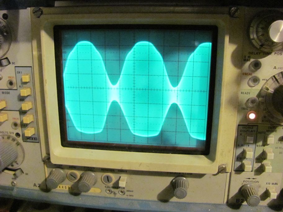
I guess I see that the modulation looked asymmetrical about the 0 volts. The negative peaks look somewhat squashed.