
Phil,
I tried moving the TH frequency down to 600. The 15 VPP stayed the same but once I got below 1300, the waveform started real distorted:
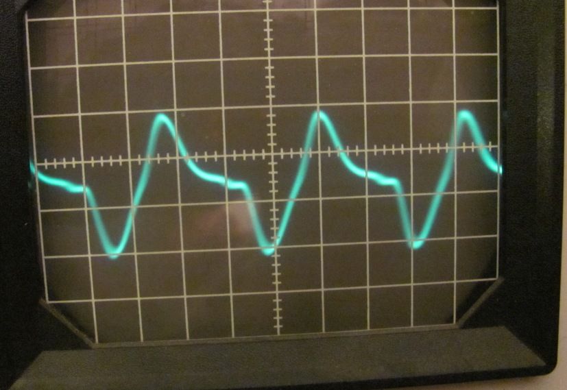
here it is at 750 KHZ (ugh! looks like unwanted harmonics, big time) What is going on?:
Perry,
The circuit feeding the external antenna jack does not have significant low-pass filtering and it is not tuned, so harmonics are to be expected. This is OK because once the coax is connected to the ATU and the ATU is properly tuned to resonance, the waveform should change to a sine wave and there won't be significant radiated harmonics.
I have no explanation for why different people are seeing different power with their seemingly identical measurement method. There are too many possibilities to even speculate.
As Neil said previously in this thread, multiplying peak voltage by .707 to get RMS voltage only works for a pure sine wave. At the upper limit, for a pure square wave, the RMS voltage is equal to the peak voltage. The RMS voltage for a random distorted waveform can't be determined unless you have some sort of RF voltage measuring instrument that displays true RMS voltage.
"The circuit feeding the external antenna jack does not have significant low-pass filtering and it is not tuned, so harmonics are to be expected. This is OK because once the coax is connected to the ATU and the ATU is properly tuned to resonance, the waveform should change to a sine wave and there won't be significant radiated harmonics."
Not quite. Try hooking one up to a spectrum analyzer and see for yourself that the tuning of the ATU, internal or external, does not "significantly" tune out harmonics. If you look inside one, or even look at the schematic, you will see the unit has a broad filter design in front of the toroid. It's not very effective, but brings the harmonics to the required minimum of -20db down from the fundamental.
A spectrum analyzer will confirm this. I've done it myself and the Motorola R 2012 D and HP 8590 are highly precision spectrum analyzers and comm's analyzers.
The TH output network is broad band, the internal auto ATU for the wire and the external ATU for the whip does the tuning.
"I have no explanation for why different people are seeing different power with their seemingly identical measurement method. There are too many possibilities to even speculate."
Let me jog the memories. These TH units are not built with precision parts, all with 10 percent +/- tolerance and mass produced over in China. It was pretty much concluded by YOU GUYS that the reason for the variance in power and audio performance was due to the wide variance in component tolerances. I even agree with those conclusions. I've got two TH V5 units sitting here and both perform differently to each other. One has great sounding audio and range, the other..less than optimum for what it is..even it's own internal audio source sounds like garbage as well as displays crappy waveforms on it's own.
"As Neil said previously in this thread, multiplying peak voltage by .707 to get RMS voltage only works for a pure sine wave. At the upper limit, for a pure square wave, the RMS voltage is equal to the peak voltage. The RMS voltage for a random distorted waveform can't be determined unless you have some sort of RF voltage measuring instrument that displays true RMS voltage."
The unit puts out a sine wave. With a known good scope start probing from the oscillator and through the two buffer stages, then the final. The carrier frequency is not digitally generated. It is a simple PLL controlled oscillator.
Unless a known sine wave test signal is ran through that scope and verified it's displaying correctly, anything you pipe into it won't be displayed correctly thus any reading or measurement will be useless. That is an old o-scope..a kit to be exact, and have you had the caps and V and H deflection circuits tested and adjusted properly? It will have calibration adjustments inside. That Heathkit is 3 decades + old, and if it still has the original caps and the internal setup potentiometers not checked for drift in value, that scope will be way off from what it should be displaying. Has the CRT been checked on a CRT analyzer? Being a 30+ year old scope...I bet that CRT has become "soft" and needs a bumping with a CRT checker/restorer.
Remember the old TV CRT's and when they aged they would display soft, weak and fuzzy? Hmm....go figure!
"Just recalibrating the scope against a known 15 vdc source and still measure 14-15 vpp. The waveform has the same peak-peak value whether I use the AC or DC setting on the scope. I doubt the unit been "souped up" because it still had a realtor's message on it when I got it from EBAY last week."
Well all that is doing is validating the V input with the setting of the V input knob. It doesn't validate if the sweep rate purity is good..ie the fuzzy display at increased sweep rate. Ebay eh...well unless the seller validated and provided evidence that Heathkit was shotgunned with new caps and pots inside, I wouldn't trust that scope to display anything correctly..not even a known 15VDC source..if that 15VDC source is truly producing a pure flat DC output too! I should also point out that checking for DC isn't checking for AC, and the AC sampling components in that scope very well could affect the signal applied to be measured if those AC input components are drifted out of tolerance from 30+ years of age!!
Phil is correct. You do need a precision RF measuring instrument to display the true RMS RF voltage, which is a high frequency AC signal..and always a sine wave at the output, or fed into a filtering circuit if the carrier is digitally generated so you have "wave shaping" taking place. Square waves shooting out a transmitter produces TONS of harmonics.
However I think most of the problem is that o-scope. It's not displaying correctly, even the displayed increase in sweep making the carrier appear as if it's "fuzzy". The TH unit doesn't do that no matter what frequency it operates on. It produces a pure sine wave across the entire band. And because that output is broadband since the thing needs to operate over the entire MW band, it also has to output a pure sine wave across that entire band. The tuning by the internal auto ATU or external one simply brings the radiator to resonance..nothing more.
It's possible that TH unit has a problem too..probably in the modulator. Combined with an unverified proper operation of the o-scope, you may very well be chasing phantom issues caused by two incorrectly operating devices..the transmitter AND the o-scope.
Process of elimination...verify that scope is operating properly across it's entire sweep range..ie V and H deflection, as well as "sweep rate purity". Grab a second scope known to be working correctly and use that to validate the Heathkit's proper operation, then test the transmitter.
If you get the same results from two different scopes, then the problem is obviously the transmitter..unless black chance strikes twice..which sometimes it does and you got two improperly functioning scopes.
A simple work around to measuring that RF output would be to build a detector using nothing more than a fast switching diode and resistor pad (3 parts), and use a DVM to measure the DC voltage produced by the detector. Google RF sensing detector and find tons of simple circuits to accomplish this.
Good luck and check that o-scope against another and make sure your not running in circles because of an improperly operating piece of test gear!
RFB
"Farther down in that thread another person posted his results."
The second set of results are more accurate than the first. That is comparing to the tests I ran going straight into the Motorola R 2012 D analyzer through a 2 foot long piece of RG-214 into the power RF input terminating with the analyzer's internal 50 ohm dummy load, which was checked and measured precisely 49.97 ohms.
Care to see the pictures? Well maybe not, photographic evidence around here lately seems to not matter and is ignored too when posted by certain individuals eh.
RFB
"Just to note that the unlicensed power permitted by the FCC for a compliant transmitter certified under §15.219 refers to the d-c input power supplied to the final r-f amplifier of that transmitter, without modulation. The legal, unmodulated OUTPUT power for those same conditions could not exceed the legal, unmodulated INPUT power -- as that would require a circuit efficiency greater than 100%."
Correct! Perhaps send Radio Systems a reminder about that too.
Ain't nothing anyone here or elsewhere can do anything about the TH's measured outputs beyond 100mW DC input. It (TH) was given the OK to operate at those slightly higher power levels to boot. I would say that the FCC has no real issue with a few extra mW or uV..since that TH currently carries a valid certification..eh?!!
You should see what the modified (questionable legality of the modifications made) iAM unit's measure! Double them from Phil's noted lists of readings..particularly the second list which is far more accurate and correct than the first. Obviously the first test list results are from an improper testing setup.
When I tested my TH V5 unit (not iAM), on 1670 it measured 135mW at the F connector. Pretty darn close to the 2nd listed results on 1650 at 144mW measurement eh?!!
Outside validation to my posted testing results months ago. Wow...imagine that! Maybe this RFB guy really does have professional testing gear recognized by the FCC and what he posts isn't a bunch of nonsense and he knows what the F he is doing..AND talking about.
RFB
I still think I must be doing something wrong. When I have this TH pushed right up against a window and the wire antenna running straight up, I get lousy range compared to the previous TH I was playing with last week (in the same configuration). By the time I drive to the end of my 300' driveway, it is almost unlistenable.
With the last TH (v5.0), I could actually pick it up pretty good to 1/2 mile and actually got some faint signal as far as 2 miles.
RFB,
I very much appreciate your detailed reply. Certainly give me a lot to think about. I'm really just trying to learn this stuff and get back into electronics again after getting out of the engineering business 30 years ago. I was hoping I could make crude measurements with my old (borrowed) scope and avoid buying a lot of expensive test equipment.
As I posted below, I really doubt this TH is putting out over 1/2 watt as I can barely pick it up at the end of my 300' driveway. My other talking house would go 1/2 mile w/ the same setup.
On the plus side, when I tune it to 540, I can pick up the signal at three places on the AM Dial!! (;>))
"I still think I must be doing something wrong. When I have this TH pushed right up against a window and the wire antenna running straight up, I get lousy range compared to the previous TH I was playing with last week (in the same configuration). By the time I drive to the end of my 300' driveway, it is almost unlistenable."
Usually with the antenna up next to a window that alone will affect performance as the window frame will seriously affect the radiated signal from the wire. However if you did notice a significant difference between one unit vs another in that same configuration, perhaps the current TH unit has a strange problem going on inside..probably in the modulator circuit would be my first guess.
The modulator feeds the two final transistors with B+ voltage (aprox half of supply voltage) and amplified audio current through a single transistor being fed by a current amplifier op amp IC. If there is any DC offset taking place in that circuit, it will seriously affect the way those final RF transistors will work, as they are entirely dependent upon that modulator circuit to deliver the proper voltage and current under both unmodulated and modulated situations.
"On the plus side, when I tune it to 540, I can pick up the signal at three places on the AM Dial!! (;>))"
Indeed! The unit has a broad band output tank so it can work across the entire AM band. There is a broad band filter after the two final transistors, but it is not a very good one but does notch down harmonics to their required -20db point per 15.209. The reason why you pick up 540 on different points on the AM band is 540's first harmonic is "in-band" at 1080, and the 3rd signal heard is most likely due to "ghost" signal produced by a mixture within the receiver's IF circuit from a nearby station. A spectrum analyzer will show the 1st harmonic when connected directly to the TH output, but it won't show the 3rd "ghost" image carrier because that is generated by a receiver and it's "front end" and IF circuits. The receiver still sees other frequencies whereas the spectrum analyzer connected directly to the TH output will be isolated from external signals, thus it's front end will not be affected.
Most measuring done in high power transmitter sites are done with very tight band pass notch filters to prevent false readings that will be produced by co-located high powered transmitters. Though not the case here, the regular radio receiver will "mimick" this effect even with very low power signals intermixing in the radio itself..thus the term "ghost image" signal.
RFB
The window that the wire passes through is all wood with no metal screen or storm window.
I figured the 3rd signal I heard was the third harmonic? 540 x 3 = 1620.
Probably...that is if the level of the 3rd is high enough to be detected. A filtered transmitter will always have a little left over as the harmonic count increases..and decreases. You will probably find the same result going the other direction..below the MW band with the same level of harmonic signals as the positive side.
Both will gradually decrease in signal level..going up or down. 1620 is a good ways from 540, but if the receiver is highly sensitive, would pick it up and sound like a strong signal. A spectrum analyzer would be needed to see it's level and verify the regular radio is actually picking up a harmonic rather than a ghost signal.
I've seen situations where a harmonic, 2nd or 3rd is notched down to as low as -60db and measure as such on a spectrum analyzer. Then taking a regular radio with sensitivity would make that 3rd sound as strong as the 2nd and fundamental carrier!
The TH units are good units IMO. But they are not built with precision in mind. They are intended to sell houses via a voice message, external or recorded internally. They were not designed for "broadcasting" in the sense of broadcasting programs or music. If they were designed for that purpose, far better specs and tolerances would have been incorporated into them.
But they are what they are and can work really well.
Noting back on the scope displays of the modulated signal, the waveform is incredibly "lop-sided" to the positive swing and quite crunched to the negative side of the waveform. That should be nice and symmetrical, both positive swing and negative swing..leading to my theory that the problem with that unit is in the modulator circuit and having a strange DC offset taking place when modulation is applied. The DC level should remain constant and only the AC component of the audio signal changing the voltage and current applied to those finals.
I suspect the modulator op amp IC to be flaky. If it was driven hard prior, that could have damaged the op amp IC's internal characteristics with respect to maintaining a steady DC offset voltage on it's output, thus operating the two finals way out of designed spec, affecting the range seriously..as well as showing up on a scope incorrectly..though the scope should not be ruled out as it could be adding to the actual problem in it's displaying of what actually is coming out of the transmitter.
Adding, actually the third harmonic would be at 2160, a multiple by 2 from the 2nd at 1080. Also the glass itself, which is comprised mostly of sand particles, will also affect a low level signal, even more so if said glass is made to change it's shade during the day, or has UV wavelength reflecting material embedded into it. But I don't think that is what is causing the unit's degraded performance. More likely an internal problem along that modulator circuit IMO.
RFB