Here's the scope trace of voltage across the 50 ohm dummy load resistor. The scope setting are on 5 v/cm (same scale as I measured my DC power supply at)
(please note that I have adjusted the Red Cal knob to calibrate the scope as described in the previous post)
Here's the scope trace of voltage across the 50 ohm dummy load resistor. The scope setting are on 5 v/cm (same scale as I measured my DC power supply at)
(please note that I have adjusted the Red Cal knob to calibrate the scope as described in the previous post)
Using a calibrated Motorola R 2012 D analyzer connected directly to the F connector output, the units run at about 135mW no modulation. The Motorola has a built in 50 ohm dummy load and was calibrated 4 months prior to the testing.
Something isn't right with your test connection, scope settings or probe type.
Adding: You might want to throw that scope to AC mode instead of DC. You are in fact measuring for an AC signal..not DC.
The displayed waveform in the photo looks as if the scope deflection circuits are off balance, or your feeding the TH with asymmetrical modulation..something the TH units are not good at transmitting. Measure with no modulation..should be a nice even fat waveform, expand the sweep and you should see a nice sine wave, even rise and fall times, not lop sided.
RFB
You get 15 V p-p with no modulation and just a little bit more p-p voltage with modulation. The modulation in the scope display is clearly much less than 100 % and unsymmetrical. I've heard that the audio in the TH is not very good. Do you think that this transmitter is working "normally"? A proper 100 % modulated AM signal should have twice the p-p voltage of the unmodulated carrier. The low modulation percentage would produce quite a bit less audio at the receiver than the same apparently high carrier power would produce in a properly functioning AM transmitter.
You get 15 V p-p with no modulation and just a little bit more p-p voltage with modulation. The modulation in the scope display is clearly much less than 100 % and unsymmetrical. I've heard that the audio in the TH is not very good. Do you think that this transmitter is working "normally"? A proper 100 % modulated AM signal should have twice the p-p voltage of the unmodulated carrier. The low modulation percentage would produce quite a bit less audio at the receiver than the same apparently high carrier power would produce in a properly functioning AM transmitter.
Ermi, Yes, the talking house is working normally. I have played music through it and it sounds as good as they usually do.
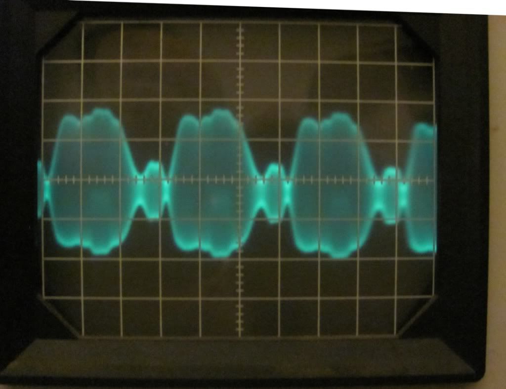
For this exercise, I just used the built-in Talking House condenser mike. I set it to record, and blew threw a harmonica (middle C, I believe) for as long as my lungs would last. I'm guessing a harmonica is not going to generate a pure sine wave. If I used the Line-in and an MP3 player, I can get more modulation.
EDIT: 10:08 est Here's a little more modulation from my Harmonica. I'm pretty sure the funny looking audio is an artifact of the tone of the harmonica. The third harmonic of the note playeed is very strong.
Ermi, Yes, the talking house is working normally. I have played music through it and it sounds as good as they usually do.
For this exercise, I just used the built-in Talking House condenser mike. I set it to record, and blew threw a harmonica (middle C, I believe) for as long as my lungs would last. I'm guessing a harmonica is not going to generate a pure sine wave. If I used the Line-in and an MP3 player, I can get more modulation.
EDIT: 10:08 est Here's a little more modulation from my Harmonica. I'm pretty sure the funny looking audio is an artifact of the tone of the harmonica. The third harmonic of the note playeed is very strong.
Duplicate post. See next post.
Duplicate post. See next post.
I have seen other measurements taken the same way. Here are measurements from another forum:
http://antiqueradios.com/forums/viewtopic.php?f=12&t=132608&hilit=Talking+House+TH+5.0+vs+SSTRAN+AMT3000+
QUOTE:
I switched the TH 5.0 transmitter to 'external' antenna and connected a 50 ohm coaxial rf load to the 'F' connector output jack through a short 50 ohm coax cable. I connected my Tektronix 465 oscilloscope across the rf load to measure the peak to peak rf voltage at several frequencies. The following is a table of my results including the calculated power output levels.
0600 khz................13 v p-p............4.59 v rms.............421 milliwatts
0800 khz................13 v p-p............4.59 v rms.............421 milliwatts
1200 khz................11 v p-p............3.88 v rms.............301 milliwatts
1650 khz.................9 v p-p.............3.18 v-rms.............202 milliwatts
Farther down in that thread another person posted his results.
QUOTE:
** two 100 ohm resistors across the antenna lead (50 ohm) across BNC "T" connector
0600 khz...............10.8 v p-p..........3.8 v rms..............290 mW**
0800 khz...............10.4 v p-p..........3.7 v rms..............270 mW**
1200 khz.................9.2 v p-p..........3.3 v rms..............211 mW**
1650 khz.................7.6 v p-p..........2.7 v-rms..............144 mW**
Here's a trace of the same signal looking at the carrier frequency. 5 v per cm
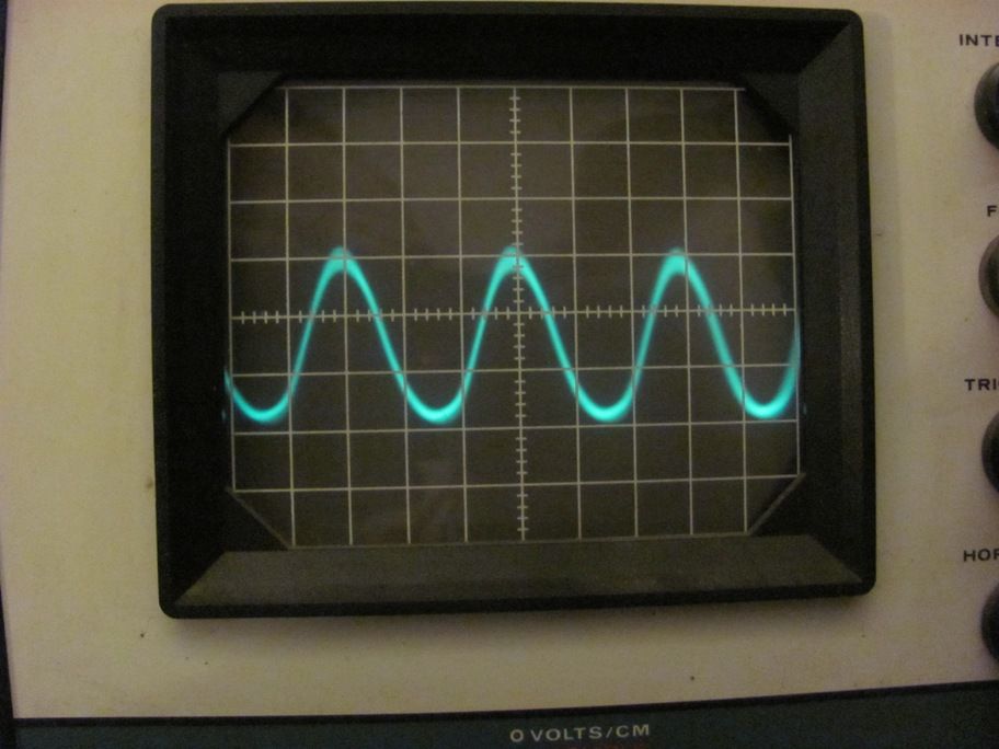
EDIT: 11:35 EST Just recalibrated the scope against a known 15 vdc source and still measure 14-15 vpp. The waveform has the same peak-peak value whether I use the AC or DC setting on the scope. I doubt the unit been "souped up" because it still had a realtor's message on it when I got it from EBAY last week.
Here's a trace of the same signal looking at the carrier frequency. 5 v per cm
EDIT: 11:35 EST Just recalibrated the scope against a known 15 vdc source and still measure 14-15 vpp. The waveform has the same peak-peak value whether I use the AC or DC setting on the scope. I doubt the unit been "souped up" because it still had a realtor's message on it when I got it from EBAY last week.
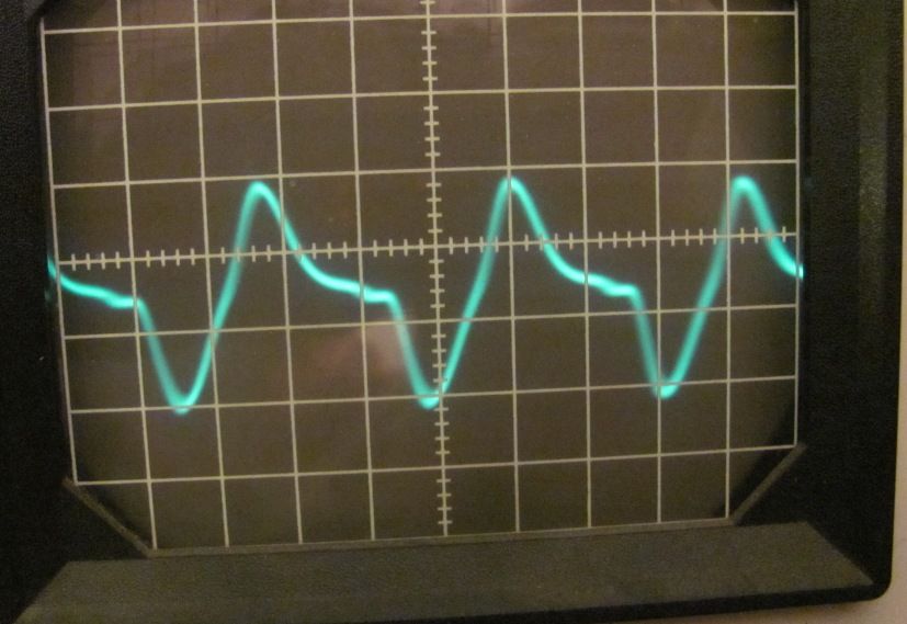
Phil,
I tried moving the TH frequency down to 600. The 15 VPP stayed the same but once I got below 1300, the waveform started real distorted:
here it is at 750 KHZ (ugh! looks like unwanted harmonics, big time) What is going on?: