
Flexible Wiggle Room
It is true as Mark says: "The rule doesn’t say anything about actual usable output as what matters…. the 10 ft. antenna."
What that means is that if the RF amplifier output stage is more efficient, you get a better field strength.
Just like if your antenna, loading coil, grounding is well designed you get better results.
@ Mark: Answering your question, since the power output is in fact minuscule < 10 mW, and with an unpredictable load impedance, it's simply easier to specify input power as V * I to determine the power whether it be transistors or tubes. Also, even if the load impedance was fixed acquiring a measurement device at such a low power levels is difficult.
With regard to "unmodulated," an AM carrier as Tim pointed out varies with the amplitude of the amount of audio applied. As with varying audio power that one might experience with music or voice the V * I measurement would not be constant. Assuming voltage to the collector or plate is well regulated, the current would have swings with modulation. Therefore for measurement purposes the power input is observed with no audio applied.
Hope this helps.
There appears be some general confusion concerning the meaning of the term "input power" as it applies to an r-f amplifier.
It is not the r-f input power supplied to the amplifier.
It is the d-c (direct current) power that is supplied to that r-f amplifier - which enables it to amplify that r-f input power.
The r-f output power of an r-f amplifier depends on the d-c to r-f conversion efficiency of that amplifier, which depends on its design and adjustment. Such efficiencies typically can range from about 30% to about 90%. They never can exceed 100% for any/all operating conditions.
So, for example, if the d-c input power to an r-f amplifier stage is 100 mW, the r-f input power to it is 2.5 mW, and its r-f output power is 50 mW, then the amplifier has a power gain of 50/2.5 = 20 (13 decibels), and its operating efficiency is 50%.
However not all of that 50 mW of r-f output power is radiated by a Part 15 AM antenna system. Nearly all of it is dissipated as heat in the matching loss resistance of the loading coil plus the connecting path of the transmit system to r-f ground (the earth).
The FCC was wise _not_ to specify an upper limit for r-f output power for Part 15 systems, because accurately measuring it requires specialized, and expensive test equipment that almost nobody would have, or want to buy.
OTOH, measuring the d-c input power of an r-f amplifier can be done by almost anyone, using a simple and cheap multimeter.
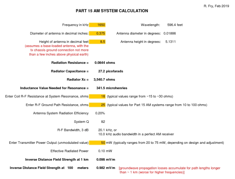
Followup: below are calculations for a ~typical, legal Part 15 AM system...

Thanks guys for explaining it!
"So, for example, if the d-c input power to an r-f amplifier stage is 100 mW, the r-f input power to it is 2.5 mW, and its r-f output power is 50 mW, then the amplifier has a power gain of 50/2.5 = 20 (13 decibels), and its operating efficiency is 50%."
That is a big help, thanks.
RE: “So, for example, if the d-c input power to an r-f amplifier stage is 100 mW, the r-f input power to it is 2.5 mW, etc." That is a big help, thanks.
Good, and thanks for saying so.