

Ok, this wouldn't be of much interest to folks using transmitters with well-engineered audio sections like the Hamilton or Sstran. But for those of us running homebrew, real inexpensive kits, or maybe some other types of transmitters I haven't worked with it may be of some use.
MORE
A "Brick Wall" limiter is a circuit or device that imposes an absolute limit on the maximum amount of audio that can go into the audio input of the transmitter. Even a simple one like I'm going to talk about here can prevent overmodulation. As was discussed in another thread HERE, cranking the audio up a bit can help with getting usable range within the legal limits of your transmitter's signal. But too much causes problems. On AM it's "splattering", on FM the problem is exceeding the allowed bandwidth for part 15. Either way, it can get you in trouble. Even if the legal aspects weren't something you're worrying about, on AM it can make your signal sound crappy and on FM you're also wasting power by putting out a signal "wider" than most receivers can handle. With either you can also damage your transmitter.
This circuit will *not* give you "125% positive modulation".. But properly adjusted, it can keep your transmitter from going past zero on the negative peaks.
Anyway, the circuit:
POOR MAN'S BRICK WALL SCHEMATIC
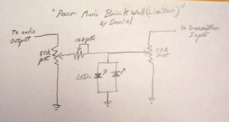
Rude, crude and simple. Only 5 parts (plus whatever jacks you add to plug it between your gear and a small case of some sort), and it works pretty well considering the low cost (cost being zero if you happen to have the parts in your junkbox or can strip them out of some piece of gear that's destined for the junkyard). The values are not particularly critical and anything close should work fine. On the other hand, it can work with a very wide range of gear. Like if you want to take the output right off a headphone jack or even the speaker of a small stereo or "boombox" with an "aux" input on it and run it into the audio input of your transmitter? This can do it, if you adjust it right. If that small stereo or boombox just happens to have an equalizer on it, it's a cheap way of adding an eq into a very low-cost sound chain and making an old piece of gear you might happen to have lying around collecting dust or find for a few bucks at the local goodwill store get back to working for it's keep.
It does need a fairly strong source signal if you use LEDs as I prefer to. LEDs vary depending on the type, but they usually take a little under 2 volts for the "standard" type. The 2 diode clamp/clipper won't actually kick in and have a noticeable affect at taming down the level until you have a signal that exceeds 2 volts on a positive and/or negative peak. Or 4 V AC as measured with a standard voltmeter. Smaller signals like the line level output from an actual mixer would need some boost to work with the circuit with the parts I show in the diagram. But small amplifiers are easy to find, scavenge or build.
Anyway, since there's no telling what the assorted transmitters people might be using out there may need for best results, I decided to keep the options wide and show a version of the circuit that can supply anything from a few volts of audio down to.. well, actually all the way down to nothing. That way no matter what sort of transmitter one might be using, this can work with it. There are certainly more elegant ways of going about building a brick wall that the tech savvy here will no doubt point out, but my goal is to post a newbie friendly project that will work with a wide range of equipment that many of us might consider far less than optimal or "professional".
Also I happen to prefer the way LEDs clip (distort) if the brickwall is actually driven hard enough for them to come into play. They have more even-order harmonics which most people find more pleasing to the ear and are a bit more reminiscent of tube/valve amps being overdriven. If you think maybe a couple LEDs can't sound like a tube/valve, take it up with the Marshall corporation who used a 2 LED clipper on their "The Guv'nor" guitar effect to emulate their own well known tube amp sound. I have one, and it's a fairly reasonable imitation of the sound of a big tube amp driven into clip (at least for how simple the circuitry in it is).
More later on how to actually adjust the circuit to work right. For now I'll declare this long enough for one post and give the tech-savvy folks here the opportunity to comment on the circuit if they feel so inclined.
Daniel
Daniel,
Thanks for sharing your project here. I especially like the use of LEDs as both limiters and indicators.
If you want to experiment a bit more, it looks as if a pot in series with the LEDs (where the leads are tied together and go to ground) might provide a way to "soften" the limiting.
Anyway, don't let me mess up your elegant circuit. I just thought you might be interested in this.
Neil
Oh, absolutely, Neil! There's a lot of things that can be done with this little circuit. It's a basic "building block". The modification you mentioned is good when you need soft shoulder as you mentioned, and another nifty trick is to use a capacitor or RC circuit in the spot you mentioned to make a circuit that will only clip certain frequency ranges and.. Well, lotsa stuff. LOL But even adding the resistor to pad the clipper would lose the "brick wall" effect, which is what we're going for here. As shown, it will only allow a signal up to a certain voltage into the transmitter. If we soft-shoulder it, it'd sound a bit nicer, but a loud enough signal would still overdrive the transmitter.
Sooo.. Back to the Brick Wall.
Ok, if you decide to build this little circuit, you can fit it into a *very* small box/space, especially if you use the little "trimpots" for the potentiometers. There is another advantage to it needing a fairly strong signal voltage (like the ouput from a small audio amp) to work, and that is that if you need to run a cable to get audio to your transmitter, it actually will give a decent sound with speaker wire or you can butcher an old extension cord rather than buying audio cable. The voltage on that line is going to be high enough that any noise it picks up will be pretty tiny compared to the signal. Maybe not recording studio quality, but certainly low enough noise for most hobby stations on a tight budget.
Now as to adjusting it to make it work, as Neil mentioned, the LEDs are also an indicator light. If they flicker, then they are clipping excess voltage off the signal. What you want to adjust for, though, is so they pretty much never come on in normal operation. The brick wall is kind of a safety valve, and we only want it to step in when there's actually a problem.
There's basically 3 ways to adjust it. By ear/eye, with a meter (DVM or an old analog meter), or with an oscilloscope (or the winscope software and your computer, since it's all audio frequency and that's what winscope is actually made for). I feel using some sort of scope is the best method, but meter works too, and "by ear" works in a pinch. At the risk of being silly, I'm going to break those methods up into seperate posts to make them easier to find and avoid confusion.
Daniel
Ok, doing it by ear is the least precise way of adjusting it, but it's fast, and if you don't have *any* test gear it still works a lot better then nothing.
First step is to *not* have the transmitter hooked up to the circuit yet.
Next step is to set your source about as loud/high as you feel you're likely to want it. Meaning it you're also that amplifier/stereo/boombox as your "studio monitor", set it to a comfortable level for listening. Then set the 10k potentiometer (which limits current, by the way) to maximum resistance. If you don't have even a meter and you aren't sure which way to turn it, get a flashlight bulb and battery or anything like that (not an LED flashlight) and check it to see which way (turned all the way to the left or right) turns off the flashlight bulb. That'll be max resistance. That's how you want it set to start.
The 10k pot limits current flow to keep too much from getting through. The LEDs are pretty robust and probably won't need protecting with the values given in this circuit, but your transmitter proobably sure will need that protection if you're driving it with wires off a boombox or stereo speaker. So set it at max to begin with, and we can back it down later to let more current through if the transmitter actually needs it.
Now check the LEDs. Cup your hand around them or turn out the lights even. If you see *any* flicker of light in them, adjust the 50k pot on the input side until it's just below when they flicker. A "test tone" running through your audio chain is easier for this than music, but very loud music without many (if any) quiet parts will work in a pinch.
Ok, now is a good time to check the sound. Hook up a small speaker or heaphone to the side of the curcuit the transmitter would hook up to. Turn the potentiometer on that side back and forth and you'll hear sound when it's turned one way, and not when it's turned all the way the other. Just like a volume control (which it is, actually). Notice if the music sounds clear. If it sounds a bit "fuzzy' or distorted, adjust the pot on the input side until it's sounds good and clean. The LEDs *do* light up when too much power is coming throug, so they are an indicator, but the pulses can be so fast and faint that they're hard to actually see, so your ears are the best guide at this point. If the LEDs actually light up when you're using this with a transmitter, you're pushing way to much power down your soundchain line and/or need to adjust the input side pot.
Ok, now turn the pot on the side for the transmitter "all the way down", so you hear nothing. Now you can disconnet the speaker or headphone and hook the circuit up to your transmitter. Turn on the transmitter and *slowly* creep up the pot on the transmitter side until you hear sound on the radio you use to listen to your transmissions. There are a few threads on this forum about how to check your modulation in different ways (including how it sounds) so I'll direct you to the search box for now. We can go into that again in this thread if necessary to clear it up a bit, but I don't want to make this post a mile long covering things already siscussed elsehwere on this forum. Adjust the pot on the transmitter's side of the circuit until you have a good level of modulation. If it sounds very "thin" or too quiet and "scratchy", then adjust the 10 k pot a little at a time, since your transmitter may need a little bit more current to drive it right. This is a 'tinker and tweak" approach, since there's no way for me to know as I'm writing it how much voltage and current your transmitter needs to deliver a well modulated signal, so you kind of have to play with it a bit and the more you learn about modulation, the better you can fine tune it.
This method is the most crude and approximate.. But it'll work better than nothing if you don't even own a cheapie 5$ meter.
Daniel
Ok, it's simpler to adjust the circuit if you have a voltmeter. If it's even a cheap DVM, the numbers can fly pretty quick, and it it's an analog multimeter or similar, then the needle won't really move fast enough to see the short peaks in music. But either can be used, and if you use a "test tone" you recorded that's just any steady pitch, then it becomes real easy.
I am going to *assume* that if you have a meter that you know how to use it to measure voltage and maybe current. If you don't, there are probably tutorials out on the net somewhere or a tech savvy friend you can meet with in person hopefully can show you. But how to use a meter or scope isn't the focus of this particular article..
So, we have the circuit laying there in front of us and we have a source and a transmitter and nothing is hooked up yet.
Hook the audio source up to the circuit, get your test tone going, and set your meter up to measure AC volts and measure across the two diodes (which we will refer to as the "diode clamp" from here on). As you adjust the pot on the input side of the circuit, you'll find a point where the voltage no longer rises as you turn the control up. Set the pot just *under* that point, that's your "shoulder" (if you were wondering what Neil was talking about with a "soft shoulder" earlier, except this is a brick wall circuit which has a "hard shoulder", meaning it doesn't change at all as the input signal gets louder).
Ok, now if you just happen to know from maybe the notes on the circuit schematic or the spec sheet what level of input signal your transmitter needs, you can just measure across the output and ground of the circuit and you're pretty much done. If you also happen to know the current it needs, you can adjust the 10k pot for that after you've got the voltage set and hooked up your transmitter and you should be perfect or very close to it.
Otherise you'll have to experiment a bit with the settings for the output side like we talked about in the post for setting the circuit by ear.
Hopefully, if you don't have a meter yet, this set of instructions being short and simple will inspire you to consider that if you look around you can get a nice new meter cheap for 5-10 bucks. They're very useful to have and learn how to use.
Daniel
Now this is also easy, and possibly the most highly cool way of adjusting the circuit because it's not only the surest, but you can *see* the circuit work.
Again, I'm assuming you know how to run the scope well enough to see a wave when testing points in the circuit.. But I'll make one exception to that assumption and say that if you're using winscope because you don't have an actual oscilloscope that you should use a 100k (or so) resistor on the "hot" wire that carried signal into your soundcard to cut back the signal so you don't fry your soundcard. Winscope running on your computer and a soundcard don't need a lot of signal to work well enough, and if this circuit is actually wired up to the output of an audio amp that 4 volt (or so) swing can be a lot more than the soundcard can take on it's line in which is expecting only maybe 6 tenths of a volt.
The process is similar to the one for the meter. Hook up the circuit to your sound source, get your test tone running through it and measure across the diode pair as you watch the wave on the scope. at some point you'll *see* the circuit start to clip. The nice curved tops and bottoms of the wave will start to get flattened. Set the input side 50k pot *just* under where that happens.
Now you can set the output to zero signal, hook it up to your transmitter and slowly bring it up until you have good modulation from the transmitter. Again, if you also have a meter and know what the transmitter is supposed to have as an input signal then this part is very easy, otherwise you'll have to fiddle with settings a bit to fine tune it.
Daniel
Enough talk, now it's time to put one together!
I intentionally explained how to set and use it before talking about building it sp the person thinking of building it would have a better idea what the circuit does in general, what the parts actually do, and how to actually put it to use.. and also so hopefully somebody building it didn't hook it up before reading that they should get the diode clipper set and have the output potentiometer turned all the way down before they *actually* go and hook it up.
I'd also like to mention that I don't normally build gear this way. I worked in a couple different electronics plants over the years, have done a fair bit of hobby building, and have at least some tools to work with. In fact, anyone who has ever built a kit or cobbled a circuit can hopefully do better than what I'm going to show here. But the point I'm making is that it *can* be done with almost nothing but a small handfull of parts and no tools except maybe a pair of wirecutters.
First, here's the parts:
![[PMBWparts]](http://i96.photobucket.com/albums/l186/RattanRadio/PMBWparts.jpg)
Now, you may notice that there's a round brown thing not mentioned in the schematic? That's a plastic lid off a can to use as a sort of crude breadboard to hold the parts of the circuit. Sure, there are many better ways to do this, but we're assuming absolute rock bottom budget and resources here.
Also one of my potentiometers is a 2 leg type rather than a 3 leg, and one is 6 legged because it was ripped out of an old stereo's tone controls. This adequately shows the point that a variety of styles of part could actually be used for this circuit, whatever you have handy or that has the looks you prefer and is (about) the same values.
Ok, so I decided on a parts placement and punched a few holes in the plastic lid for the legs of the components and wired it up with some old telephone/bell wire I had handy..
![[And here it is!]](http://i96.photobucket.com/albums/l186/RattanRadio/PMBWfinished.jpg)
Now, the actual wiring.. I'll show it, though it may give some of the more tech-savvy folks here fits and nightmares. It's not pretty and I didn't even bother to solder it. It's just twisted and crimped together..
[I'll bet you slow down to look at accidents too, huh?]
![[I'll bet you slow down to look at accidents too, huh?]](http://i96.photobucket.com/albums/l186/RattanRadio/PMBWwiring.jpg)
Not pretty, but when I hooked it up to the speaker of a small stereo and to an input of one of my mixing boards that can handle a similar input level to my transmitter, it worked and adjusted as I've explained above.
I don't need one at the moment, since I built one for my transmitter months ago. But one can hardly have a project thread without showing building at least a quick version of the circuit, and I wanted to show that it *can* be done with very little in the way of expense, tools, or experience.
If you're reading this, hopefully you look at the pics and say to yourself "Cripes! I could do a LOT better than that!" Exactly! So there's nothing stopping you, now is there? LOL
Another point I'm making is the tech talk and theory is good, it's wonderful.. But to be of any use it has to be put into practice. You can learn quicker from cobbling together a circuit and tinkering with it *while* you think and research things on the net or books and ask questions.
To anyone here who maybe hasn't ever built anything, maybe this simple circuit and my pics of crude construction (that still worked) will encourage you to buy a few parts somewhere or take them out of some piece of electronics before you throw it away and get started. This project was done very simply and shown made with very primitive materials and methods to try and encourage people to learn and make and learn some more. It can be a great help to your part15 hobby if you can make even simple circuits yourself rather than having to buy *everything*, and you can learn more about how things work rather than just assuming everything in the world is plug&play.
There are a lot of ways this circuit could be built better, there are a lot of things that could be added to it to make it even more useful and to actually look like "a real piece of gear". Even just soldering the connections would be an upgrade! On the "fancy" side, one could buy a couple small meters, cut holes on the front panel of a box so you could see the voltage and current of the signal going into your transmitter at a glance, etc.
I know for a fact many here can build better than I've shown in this thread, but my point is that even if one isn't an engineer or an experienced hand with a soldering iron, there are things you can put together for your station. A point I'd like to make to the more experienced folks here is that if all we do is tell people not to overmodulate and what technical and legal troubles it can cause, that's excellent, but it's only part of the answer. To encourage the hobby in positive directions, we also want to show ways things *can* be done. There have been some really great projects shown here, mostly antennas. I thought it would be good to show an audio chain project for a change that can help a hobby station sound better and avoid putting out illegal interference due to overmodulation.
Daniel
At the risk of boring everyone with yet another post on the brick wall limiter I'll mention a couple points..
You don't happen to use an audio source anywhere near that large, like you have maybe a nice mixer board and eq? Cool! Then use different diodes. A pair of typical germanium diodes will give a peak to peak voltage of about 6/10ths of a volt or so, which is pretty close to line level, and if you're sure your transmitter won't need *more* than that, it's an easy way of adapting the circuit. If you needed a little more, you could check diode specs and find ones to fit your situation. You also could use smaller pots if you like. But the circuit as given was for gear that might be a long way from a "professional" setup right now.
Also if a complete newbie builds the circuit and somehow got confused on what side was the input and what side was output, the tech-savvy here may note that it'd actually work the same even if it was connected backwards between the audio source and the transmitter and so long as the instructions were followed on adjustment it still would be unlikely to harm the transmitter. And yes, that was intentional.
Daniel
Daniel,
Thanks again for the great description of your project.
The technogeek in me is urging me to add a few comments which I hope will enhance what you have posted.
Slight correction, symmetrical clipping on the top and bottom of a signal adds primarily odd harmonics. Minor picky point of no importance here.
As you have said, it is a good idea to limit the audio into and AM transmitter to prevent the dreaded overmodulation which pinches off the carrier to zero. This produces lots of "spurs" which cause interference and rob power from the signal. I want to point out that hard limiting (clipping) of the audio has the same effect even if below 100% downward modulation.
Now, back to your circuit. Diodes do not suddenly switch on when a certain voltage is applied. There is a region of operation (the "knee") where the current increases slowly as the voltage is raised. This voltage is lower than the usually cited forward voltage drop, and for an LED can be just a few tenths of a volt. This is good because it means that diode limiting is sort of a soft limiting which avoids the spurs if the audio drive is not too high and also that limiting can occur at realistically low audio voltages.
You gave some guidance on how to set the pots in your circuit and, if followed, it should be just fine. If you get a chance to look at your modulated signal on a scope, I think you will find that you are really not getting "brick wall" limiting, and nor do you want to.
Neil
Hi Neil
Yeah, I probably should have said that the clip "more resembles the sound of even order harmonics" rather than that it actually is even order. I can say (because my ears tell me so) that different diodes clip differently enough to hear a difference, silicon being the more harsh and LEDs being the more "mellow" sounding, with some germaniums being close to the LEDs in sound.
The hard clipping *can* cause problems in some circumstances, I agree. But adjusted following the instructions I gave, the circuit will only actually clip on sudden loud transients in normal use. Which is all we really were going for here, it's not intended to be used as a compressor, just as a safety valve. Good point on the mostly square wave being capable of causing some problems with spurs even a little below full 100% modulation. I didn't think to make mention of it because a.) I use an analog meter to set/check the voltage in to the transmitter, and they "average" more than scope does.. b.) most inexpensive transmitters' modulation circuits won't actually go *all* the way to 100% anyway. Maybe 85% or so before most of them begin to sound distorted. But that can still sound quite good with enough drive so you're actually getting it and the occassional transient peaks being clipped down so the modulator doesn't actually go into overload.
And agreed, it's not a "brick wall" in the modern understanding of the term. But it's actually quite close to some of the ones they used to call a brick wall back in the golden age of radio when they used circuits that were very similar to this one (except for using tube/valve diodes instead of semiconductor diodes).
And some of what you said also reminded me of one other point.. When first hooking it up, *check* between the "hot" leads on the transmitter and the audio source to make sure there's no DC voltage measurable between them. If there is any at all, add a capacitor, maybe .47 mfd or so, before the output to the transmitter. It's unlikely, I don't think I've ever seen a transmitter that didn't have a blocking capacitor in it's audio input and most sound sources don't have any DC present in their output anyway, but it only takes a second to check. If there *is* a DC voltage between the "hot" (non-ground) leads of the source and the amplifier, it could throw of the bias voltages in the transmitter causing all sorts of bizarre things that are hard to track down. It's real easy to take a few seconds to check for, and easy to fix if it actually is present.
I'll be the first to admit the circuit isn't perfect, but for the price it's hard to beat, and it's simple enough for an aspiring DIYer who is maybe looking for a little something they can make for their station (using the germanium variation if they have a line level mixing board) to get it to work a bit better and avoid some possible problems. That's all I was really shooting for with posting it here, and input from the tech-savvy here on other options or on how and why it works and etc are most cheerfully welcome.
Thanks again Neil, excellent points as usual.
Daniel
Daniel,
You certainly understood the technology in my post and I am sure the spirit with which I intended to add to your project.
Anyone with any questions should just read Daniel's previous post because I think he responded to me very well.
And don't be afraid to build one and try it!
Neil
I just read an article from one of the broadcast rags and I stumbled into a great suggestion from an engineer. He uses Cool Edit (Adobe Audition) to generate 400 and 1000 hz tones. Sometimes he mixes them. Then he saves them to a cheap mp3 player, I use a 1Gig SanDisk SANSA (79 bucks at walmart) and drive the transmitter with the mp3 player. Cheaper than a signal generator and portable. For those who do not have Cool Edit email me for whatever tones you need and I will send them to you at no extra charge.
WDCX AM1610 Part 15
John
Owner-Operator-Chief Engineer-Program Manager
Thanks for the Tones idea!
If you'd like to email those to me I can post them on the site, too
scwis at yahoo dot com
Experimental broadcasting for a better tomorrow!
Enjoy.
WDCX AM1610 Part 15
John
Owner-Operator-Chief Engineer-Program Manager
Thanks to John's effort and generosity, here they are:
Experimental broadcasting for a better tomorrow!