
What is the 2nd plate of an antenna hat? Is it the air?
Actually the 2nd will be your ground plane, or ground radials under the surface.
Know of the antenna called an "Isotron"? It is basically a "compressed" version of a vertical with a ground system. The Isotron has two cap hats, one on top, one at the bottom. The Isotron requires no ground radial system.
RFB
a lawyer friend and study partner told me "Just read the damn rule. What does it say and what does it not say?" This was good advice.
Tell that to the field agent! He may say "A-OK" and may say "NO-U-nO-Go"
I wonder if that lawyer friend simply says in court "just read the damn law, what does it say and what does it not say"....boy if it worked like that, court cases would be said and done in 10 seconds flat!!! Record breaker!! 😛
RFB
After dwelling on the matter for awhile amid frowned pacing, I come back to the witness stand.
Now that we know the "top hat" is a capacitance plate being countered by the ground as the other plate, given that they're 10-feet apart, the actual capacitance must be very very small, maybe nano-Farads or less. That wouldn't be enough to do anything in an ordinary circuit.
Don't we really need to get those plates closer together for some serious capacitance up in the Farads?
"I suppose if I removed the 350 engine in my 68 Camaro and threw in a 67 Olds 440 engine and replaced the steering wheel with a 78 Pontiac Firebird steering wheel..the vehicle will no longer be a GM product. :/"
Maybe not, but it'll gofasta! ... 'specially with the Firebird steering wheel 😉 ... put a Saturn emblem on it, too! That'll really confuse people. You could tell them it was GM's final attempt at creating a nostalgic conversion.
Anyway, just put in a new radio (new Honda radios work great ... but the antenna might be part of the reason) ... and you'll be happy 😉
The reason I call it fishy is because just adding "capacitance" without knowing the target value nor the actual values being reached is a fishing expedition in which you mostly catch imaginary fish.
What if the capacitive relation to ground, in addition to the TOP hat, had the 10-foot vertical pole flare out at the bottom to present a 12" (approximate) capacitive relation at the ground. Maybe this would catch more fish.
And hey, I'm not being silly to dismiss the interest of this discussion, this line of inquiry is entirely what this forum/blog is all about.
I am struggling to get a grasp of what we are trying to achieve and how to gain more control over it.
I thought about it awhile ... trying affix a top hat to a whip antenna ... it would sway so much in the wind, it would foul the signal. You'd have to put guys on it to stabilize it ... or replace it altogether with a (heavier) pipe.
Then it will become the GM Nostalgia Conversion Kit 😉 Probably wouldn't tune correctly in either case.
given that they're 10-feet apart, the actual capacitance must be very very small, maybe nano-Farads or less. That wouldn't be enough to do anything in an ordinary circuit.
Well for one, a 10 foot antenna at wavelengths that even 1/4 long requires at least 120 feet, were not talking about any ordinary circuit there are we. !!!
Also take into account what is in between these spaced out plates...no they are not on some wild tripped out resonant ride vibrating to psychedelic modulation! Well that would depend on the operator I guess!
The capacitance would be the result of everything combined right up to the point of connection between all that and the final coupling in the TX. As you know, series capacitance reduces value, parallel increases value..the opposite of joining resistors in those configurations.
With a top hat we are merely providing the antenna circuit with more capacitance by adding the upper plate.
Take a regular ceramic capacitor disk. Note how some of them actually show the leads contacting the plates. Let's reduce one of the lead's contact area and/or the size of one of the plates. What happens to the value and capacity of that part performing its job?
Lets put it this way....if you could add a top hat the same size as the ground radial system...ie a very large version of a small ceramic disk capacitor....well its pretty easy to see you would turn that un-ordinary circuit into an ordinary one! 🙂
RFB
Anyway, just put in a new radio (new Honda radios work great ... but the antenna might be part of the reason) ... and you'll be happy 😉
Well I would be very happy indeed if that replacement radio was AM Stereo! 😉
RFB
The reason I call it fishy is because just adding "capacitance" without knowing the target value nor the actual values being reached is a fishing expedition in which you mostly catch imaginary fish.
Well like I was explaining to a former member in an email conversation....theory and real world rarely mesh. Tis why in the engineering world you have to account for the "wiggle" room, ie room for those unknown variables. There is no "target" value until you account for everything your dealing with outside of a set of formulas and calculations.
What if the capacitive relation to ground, in addition to the TOP hat, had the 10-foot vertical pole flare out at the bottom to present a 12" (approximate) capacitive relation at the ground. Maybe this would catch more fish.
Now your "catching" on! If we add a top hat relative to the size of the ground radial size, or ground hat, you have a very large area to catch the fish with...or in the case of the radiating antenna, more area of footprint to emit the signal.....or in the case of our little friend the ceramic capacitor disk...more MojoFastDuce to zoom on down the road! 🙂
RFB
If you push a parallel element not physically attached (with a over hanging top hat OR NOT) you made a reflector (aka Yagi) and will change the signal. Will it be legal? Leave that to the others, but you will change the gain in one direction up, down in the opposite.
If you want to increase gain in one direction than a LOOP is the way to go. Taking 3 meters of copper pipe and making 3/Pi = 1 meter dia magnetic loop, it would be a FANTASTIC antenna, giving you excellent gain in two directions (with proper matching). I see nothing illegal about that in THEORY, no dimension is greater than 1 meter in Dia, 3 meter in circumference, but it is not up to me. It is up to the local FCC agent. From what I read the FCC gives people warnings. It is the repeated disregard to flagrant violations that gets you in hot water. I have no problem with a loop antenna for transmission regardless. Here is one design antenna and transmitter in one clever little package .....
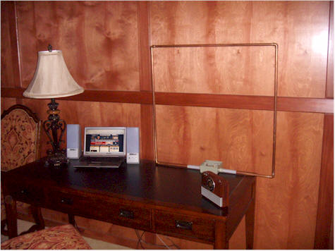
Here are some portable Ham loops, easy to convert to MW. The good news, they are simple and efficient. The bad news to resonate at 1700 Khz ideally a 20 meter dia loop would be better than 1 meter dia. You can still tune it with a capacitor. Since we are not dealing with watts, don't have to worry about arching an air capacitor or tuning over a wide range of Freqs like a Ham would want, with one loop.
Although most of these bottom out at 3.5 Mhz it's food for thought
Info (says receiving but most applies to transmitting as well)
http://www.w8ji.com/magnetic_receiving_loops.htm
I am not sure about coil loading a Mag loop, but experiment. Join the yahoo magnetic loop group, put it out there. Hams go down to 160 meter (1.8-2.0 MHz) and "lowfer" (Low Frequency Experimental Radio) around 136 Khz and will have some good ideas. The is could be the ULTIMATE Cheater or Unfair AM Part 15 antenna.
http://www.bulldogtrust.com/index12.ht
http://www.iw5edi.com/ham-radio/?make-a-magnetic-loop-antenna-for-7-21-mhz,84
NOTE: Not of these comments are intended as express permission or approval. FCC Part 15 requires the operator (you) to assure compliance with applicable CFR's.


50' tower, triple guys, 6-radial hat, 16 at 50' buried ground radials.
Very classic professional installation.
Those sky hat radials look exactly like upside down ground radials.
Yep..a classic style and very effective. Now that would be a fine example of how a LPAM licensed setup would be like.
If only.
RFB
Valcom-Guelph, a Canadian company, has gained U.S. type acceptance of a prefabricated short vertical that has surprising efficiency. Below is a link to the antenna site. Take a look at the top-loading and the construction.
http://www.valcom-guelph.com/products/V-33075AM-CL2.html
Some of these antenna systems are up to 90% efficient with a ground radial system only 240 feet in diameter; much smaller than a 1/4 wave tower system. And the best part is they are tip-up installations instead of using a crane to hoist it into place. Under special order these "whip" antennas can be built to handle 10 KW.
If you want to increase gain in one direction than a LOOP is the way to go. Taking 3 meters of copper pipe and making 3/Pi = 1 meter dia magnetic loop, it would be a FANTASTIC antenna, giving you excellent gain in two directions (with proper matching). I see nothing illegal about that in THEORY, no dimension is greater than 1 meter in Dia, 3 meter in circumference, but it is not up to me. It is up to the local FCC agent. From what I read the FCC gives people warnings. It is the repeated disregard to flagrant violations that gets you in hot water. I have no problem with a loop antenna for transmission regardless. Here is one design antenna and transmitter in one clever little package .....
Gmcjetpilot, Very interesting thing to consider.. I would actually prefer to make my signal directional if it resulted in that signal actually going farther.. That's what's unclear to me about directional signals; does it really travel farther - or just simply specify a direction?
But that aside, for the time being I'm just going to go with the certified whip installation before trying something different...
My intention was to figure everything out, - and then do it.
But now, I'm changing strategy to; Just doing it - and then figure out what I'm doing later!
I have to, otherwise my station is never going to get past my "thinking" stage.
I really have to get moving, it's gotten ridiculous.