
Ok, let me start off by saying that I don't figure that this is any "holy grail" miracle antenna. It's just an idea that occurred to me in the course of hearing why some people want to mount things up on a mast. What I'm wondering is if the idea might be worth the bother of trying and if it is a known type of antenna, etc. Seems to me someone must have thought of it before.
Anyway imagine we have a 3 meter pipe mounted vertically within a few inches of the ground. Lets say a foot or less off the ground. For the sake of the example let's imagine it's the 1 inch diameter copper pipe that we've often used in examples. It's mounted in some way to be mechanically stable but with no immediate conducting path to the ground. Basically a very plain part 15 AM antenna with no transmitter attached yet.
Now here's where it gets different. let's say we mount the transmitter (in a weatherproof plastic container, for the sake of argument) at the TOP of the antenna. Obviously the antenna connection of the transmitter goes directly to the copper pipe via a very short heavy gauge copper wire so we have no "feed line" to speak of.. But we take the ground wire and bring it down the inside of the copper pipe. Let's say we use a couple small plastic spacers and pull the ground wire taut enough that it's going right down the center of the inside of our hollow metal vertical radiating element (the copper pipe).
Now, so we don't have to account for them separately, lets say our audio and power lines are bundled with the ground wire. Let's further take advantage of the design by using a shielded multi core cable with the shield used as the ground wire so that everything shares one ground (which should help a good deal in eliminating ground loops, though that is probably more of an audio concern).
Now, where that cable exits the bottom of the copper pipe, we ground that shield to the usual copper stake pounded into the ground right next to whatever is physically holding up the copper pipe we're using as the antenna. The cable continues underground to the studio, where we can hook it up to the audio feed and power supply. But the important bit here is we take it into the dirt as directly as possible.
Ok, as a last practical touch, we can put something like a heavy plastic cylinder like a piece of PVC pipe or something around the exposed section of cable that is between the dirt and the bottom of the copper pipe antenna to provide physical protection against lawn mowers, weed-whackers and etc.
Ok, assuming I've explained that well enough that it's understood, here's the questions..
a.) how might it work differently than mounting the transmitter near the "dirt" and the antenna above it? Meaning basically would it be likely work a *lot* worse than the more standard bottom fed concept?
b.) how much of a problem might it cause to have the ground wire *inside* the radiating element? I'm thinking that due to skin effect the copper pipe antenna wouldn't be much affected one way or another by having a grounded wire going down the center of the interior, but on the other hand I can see where at least some capacitance would be involved.
c.) I'm *thinking* that since the ground wire would be inside the (metal/copper) antenna, it would provide no radiation advantage. Or any small amount that it did contribute (if that assumption was incorrect) would still be confined to the 3 meter antenna that is non-resonant at AM BCB frequencies because it is extremely short. Well, other than the very short space between the bottom of the antenna and the ground, but very little radiation would be likely to occur there since in this example we specified that distance would be a foot or less.
d.) In your opinion, would this be likely to be viewed as a 3 meter length antenna for the purposes of part 15 compliance or would it have to be viewed as 6 meters?
Those are my questions for the tech-savvy folks here. Any other comments or observations are also appreciated.
Like I said, I don't think this would be any "holy grail" miracle antenna by any stretch of the imagination. I seriously doubt it would work better as an antenna than mounting the transmitter at ground level and having a 3 meter copper pipe going up. 3 meters of vertical antenna is 3 meters of vertical antenna. But this is an idea to possibly address some complaints concerns I have seen voiced about mounting the transmitter at ground level.
The complaints (which certainly seem to have some validity) are vandalism, accidental damage, and the possibility of water damage. This would put the transmitter itself 10 feet above the ground without being one of the "whip and mast" designs that actually put the top of the antenna 20 ft above the ground or higher.
So far as it being an "eyesore" in a yard.. Well even a cub scout could cobble together a small light pine fake birdhouse to further hide the transmitter. Lots of people who'd think a transmitter on top of a pipe was an eyesore might not give a second glance to a small birdhouse.
But anyway, could this work and might it be at least one practical part 15 AM solution to consider for the "don't want to mount the transmitter on the ground" objection?
Daniel
If this antenna is fed at the base of the ground wire, with a short-circuit between the ground wire and the pipe at the top, it is called the subject-line name, or a "series-fed skirted monopole." Its advantage over an ordinary monopole is that its input reactance is lower than without the "skirt." The skirt diameter must be large in order to get the reduced input reactance, but a large diameter skirt does not increase the radiation resistance much. A small diameter skirt gives about the the same radiation resistance and input resistance as an ordinary monopole the same diameter.
An NEC simulation can be used to model this antenna, but it would be very complicated to model the skirt. This antenna is a length of coaxial transmission line. It would be easier to model the antenna as a parallel-wire transmission line. The parallel-wire transmission line will not accurately model the coaxial transmission line, but studying the parallel-wire transmission line may give us some ideas.
I modeled a 3 m antenna with two parallel wires separated by 6". At the top, the parallel wires are connected together by a wire 6" long. At the bottom, one wire is connected to ground, and the other wire 6" above the ground.
If the RF voltage source is at the ground end of the grounded wire, at 1.7 MHz, the radiation resistance is .13 ohms, and the capacitive reactance is 2.7 k ohms. If the RF voltage source is at the middle of the 6" wire joining the parallel wires at the top of the antenna, the radiation resistance is .062 oms and the capacitive reactance is 3.5 k ohms. If the separation between the two parallel wires is increased from 6" to 1.5 m, and the RF voltage source is connected at the center of a 1.5 m wire joining the parallel wires at the top, the radiation resistance is .13 ohms and the capacitive reactance is 3.5 k ohms.
By analogy, I think that the shirt-loaded monopole fed from the top will work about the same as an ordinary monopole if the diameter of the skirt is large; but I expect that the radiation resistance to become smaller as the skirt diameter becomes smaller.
Top fed with no short.
Coax would be pretty close to the idea, if you fed the "outer shield" instead of the center conductor and used what would usually be the center conductor as the ground. But the diameter would be wider than coax and it'd be an air dielectric.
Basically enclosing the ground lead inside the radiating element.
I'm probably not describing the idea very well, I'll try to scribble up a diagram or something.
Daniel
Here's a quick sketch to hopefully clarify the idea..
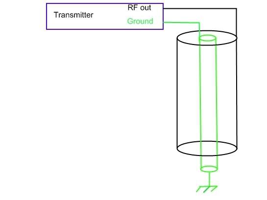
For the sake of discussion, let's assume the intentional radiating element of the antenna is a copper pipe 1 inch (25 mm) in diameter and 3 meters long. It would be represented in the sketch by the black cylinder.
The ground is shown by the green cylinder, and let's assume it to be approx 5 mm.
The ground is enclosed by the radiator except for the amount at the bottom which is necessary to take it into the "dirt", and wouldn't be longer than is necessary to keep the copper pipe from being shorted to ground by grass, weeds, rain, etc.. Probably a foot or less, so for the sake of argument lets call it one foot or approx 30 cm.
In practice it probably wouldn't need to be even 30 cm, but I'd guess that would be typical for the actual distance between the ground terminal and the point it enters the actual soil if a transmitter is mounted at ground level. Obviously we don't want the copper radiator touching the soil, but basically we'd be trying to use the minimum reasonable and practical distance to accomplish that.
For the sake of simplicity, I have not shown power supply or audio wires or etc. Those would vary depending on the particulars of the transmitter, and would be inside the green cylinder and using the green cylinder as their ground (and audio shield if necessary) to avoid having multiple ground wires each taking a separate path to the transmitter. Which makes sense for avoiding ground loop effect "hum" as well as minimizing any contribution such connections otherwise might make to antenna length or radiation.
Daniel
PS (added on the edit).. all leads would be kept as short as possible. Since transmitter designs and connector choices vary, it can be ignored for the moment or whatever amount one feels the practical minimum can be used.
Daniel,
Without going into a detailed analysis of your proposal let me state that a coaxial line will radiate a signal if the currrent in the center conductor is not equal to and opposite in phase with the current in the outer conductor (shield).
There is no difference between a shield on a coaxial feedline and a solid conductor when the shield is exposed to an external RF field or is returning the RF current induced and collected from the earth ground back to the transmitter. If this return current in an outer conductor with a coaxial antenna contained within is equal and opposite to the antenna current then radiation won't happen. If radiation is happening then both the antenna and ground lead are contributing to it due to unbalanced currents. [itailized comments edited in for clairity].
At VHF and microwave frequencies we can decouple the shield from these currents using stubs but we rely on other methods to collect the return current such as radials at the bottom of the antenna. A 1/4 wave stub, practical above about 100 MHz will provide an open circuit to the shield return currents and reduce or eliminate feedline radiation, but to radiate we use radials or a dipole arrangement to return current to the transmitter. With this setup it is practical to keep the feedline currents balanced and minimize feedline radiation. To do so at AM broadcast frequencies requires too much real estate. The closest we can come, as far as I know, is to collect the ground currents and return them to the tranmitter through a short ground lead. The ground lead will radiate, even if it is a coax, and by keeping it short we minimize the radiaton. The feedline can be installed so it does not radiate providing the collected current from the ground returning through one side of the line balances the feed current through the other conductor of the line, but simply using a "shielded" line does not make this happen.
Neil
I understood the written description of the proposed antenna exactly like the diagram shows. Remember that an ideal voltage source, by definition, has zero internal resistance. A real voltage source has finite internal resistance, of course, but it is convenient to simplify a discussion about antenna theory by assuming ideal conditions.
If the voltage source is moved from its assumed position at the top of the antenna to the bottom of the ground wire, the rules in circuit theory governing superposition require a short circuit at the top of the antenna. If the voltage source is at the bottom of the ground wire, the antenna is of a well-known type, as I pointed out in my previous post. If the radius of the pipe is small, like is assumed in the description, the antenna with the voltage source at the bottom of the ground wire will work about the same as an ordinary monopole with the same dimensions. However, if the voltage source is at the top, as was originally proposed, the radiation resistance will be very low, and this design will work very poorly. However, if the diameter of the pipe is made large (like a meter or more), the antenna will work about the same as an ordinary monopole the same height. So, this particular antenna design will not work well when the pipe diameter is small, and it has no performance advantages over an ordinary monopole the same height if the diameter is large. Of course, if the pipe diameter is in the order of a meter, or so, something like a screen mesh, or several vertical wires suspended in a circle, would be used; not a solid pipe.
Thank you, Ermi Roos and Neil.
I wasn't looking at it for an advantage in gain. What I was looking for was a possibly acceptable solution to the complaint some folks have with ground mounting the transmitter. If it had been a possibly workable idea I might have considered trying it since snow on the ground in this area in the winter is often more than "a few inches" and even a "watertight" box can be cracked enough to leak by the ice and the repeated remelts and refreezes in northern areas. (Yes, before anyone asks, I'm familiar with the ones approved for outdoor electrical service that allegedly are made to hold up to such conditions. I've seen a number of them broken over the years by weather, causing assorted electrical problems for folks.)
But in any case, apparently it would be more likely to work considerable worse than a plain bottom fed vertical.
If I had been thinking, it would have occurred to me that this design would be a beast to model anyway, probably at least as much of a complex mess as the "cage" type antennas.
Thank you again.
Daniel
Rattan,
I think it is excellent that you are thinking about this issue but I do have a concern, and it is a policy issue, not a technical issue. Let us suppose that we were to come up with a way to address some of these "complaints", of which this is just one that has been raised recently. The next thing that will happen is that a certain individual will fire off an e-mail to his favorite FCC agent pointing this out, asking if it is OK or not. The answer, of course, will be that if it actually allows for somewhat efficient operation, it will be disallowed, because that is NOT what the FCC wants. Their objective is total control of the use of the broadcast bands such that you can't do anything useful on an unlicensed basis. I understand and agree with their philosophy up to a point. You cannot allow a zillion people to just go on the air and do whatever they want if their signals will actually cover a significant area. On the other hand, I think the rules were fine as they were, before being "interpreted" for us by this particular agent.
Actually, this ground mounting issue is only one of several very serious implications of these "interpretations". If you are not allowed to even attempt to match the impedance of the antenna, then there will be no possibility of making any kind of antenna radiate more than a few feet. For example, consider a 100 mW input transmitter terminated in an appropriate resistive load. The transmitter must be electrically isolated from any sort of ground whatsoever, including the mains wiring. You are allowed to attach a 3M wire to the output. That wire will have a couple of volts superimposed on it, not the usual 100 or more. And if the transmitter is truly "floating" with respect to ground, the only "ground" it will have to work against will be the PC board the circuitry is built on.
As far as I can tell, if these "interpretations" actually become codified in the Part 15 rules, they will mean the END of any useful Part 15 operation. I am not sure that there will be any approach that could be used to overcome them, but I can tell you one thing; I will not be presenting my ideas online where some geek can phone home to the FCC and immediately get them nullified.
There needs to be a forum where good ideas can be discussed and critiqued without the exposure that comes with discussion on the public Internet. I am not sure how this can be done, however, other than creating a private group with members being screened very carefully by the moderator.
As a footnote, my station remains off the air at this time due to concerns raised by the "interpretations". I am not made of money, but I will be exploring possible legal safeguards and responses to this issue. I think it is a very serious matter for all of us who value the use of Part 15 AM broadcasting.
Thoughts?
I understand what you're saying, WEAK-AM.
But if we censor ourselves by saying "Oh, it's no use anyway..", does that help? I think a lot of people in this hobby hope to make a positive difference on the public airwaves. Whether one thinks of one's range as "2 miles" or "250 ft" or "100 ft", seeing it as something that doesn't matter is just buying into discouragement. Censoring ourselves to the point of not even trying to come up with new ideas or a way to use what is allowed is just giving up. That won't help anything.
So what will help? I'll say that now, just to save anyone wondering as to my thoughts on the matter the effort of sifting through what might be a long post.. I think the people that should be talking to the FCC are the people who sell gear, especially the certified gear. They are the people who can say "This many people have bought our units so they can legally participate in this excellent activity. We find this very encouraging and are continuing to develop features to make it easier for them to be good citizens on the airwaves."
A good example of such a feature was the recent addition to the Rangemaster of the LED to show if it is operating at the intended certified power as a stock feature instead of an option that can be purchased separately. It eliminates some of the possible ways the transmitter could be accidentally maladjusted so as to be over the certified spec for power.
That's the sort of thing that could reassure the folks at the FCC that consumers and manufacturers actually have an interest in operating legally. An interest in developing further ways for part 15 BCB activity to be a legal and enjoyable hobby activity for people without risking unnecessary interference.
Just demographics, doesn't have to be a list of who bought what where, just the "bottom line" of "there are people out there who enjoy this hobby and put time and money into it." And stressing how they as manufacturers are continuing to work on new features and products to continue and encourage the trend.
But I don't feel that censoring ideas will solve anything. Historically it never does. If one wants change, one presents it in a positive light and shows how it can be done within the rules.
Now about the "certain individual" you have mentioned. I never saw his point of view as harmful or unwarranted. A traffic sign says "Speed Limit 45". It is "black and white". It does not say "You can get away with 50 on a clear day when traffic is smooth and road conditions are good", nor does it say "45 unless it's raining in which case drop it back to 40 or so". The letter of the law is nearly always black and white. Any "grey zone" that exists will exist in the judgment of a police officer or the judge if it goes that far. If anyone calls the police barracks and asks, they'll be told "The posted speed limit on that part of the road is 45."
If you want that changed, covering the signs or spray-painting them to read "Speed Limit 145" is juvenile and will cause more trouble or even injury rather than helping the cause.
So I fully support that individual's right to have his say.
This is not to say I agree with everything in his point of view. I consider "certified" to be just as much of a black and white issue. To debate if a unit "should" have been certified is a moot point. If you are going to trust the judgment of the FCC when asking a question, in my opinion it is only logical to also trust their judgment when they say a given unit is ok for use, at least if it is used in a manner consistent with the conditions under which it was certified and etc.
To me, that is as black and white as anything else in the rules. But that's *my* point of view. You have your point of view. The "certain individual" has his point of view.. I think that to find answers we need them all, and self-censoring will be counterproductive in the end.
Is there any point in asking the FCC to continue to support the part 15 BCB activity by certifying units and to perhaps even consider allowing a little more if it is shown it can be used in the public interest?
I do not know. But I personally do not believe we will find out by shutting up or telling others they should shut up.
If you ask for nothing.. that is probably the *only* time you stand a real good chance of getting *exactly what you asked for.. Nothing.
Daniel
Thanks for your efforts to encourage others! IF the FCC had any concerns about our discussions, or our activities, I am supremely confident we would hear from the FCC directly.
Should that ever happen we would promptly share anything we receive.
It is difficult to feed a 3 m monopole from the top, but there are things that can be done to overcome some of the problems related to mounting the transmitter at the level if the earth.
It has already been mentioned on another thread in this Forum that the area where the monopole is to be mounted could be built up slightly so that it forms a small mound that avoids flooding at the base of the antenna.
At one time, I had unintentionally built a mound in my yard by having a load of topsoil delivered, but not using all of it. When the topsoil was delivered, the dirt was far too loose for installing an antenna; but after several months, the mound became firm, and grass grew on it. Nobody would want to wait long enough for the mound to form naturally, so the mound would have to be packed down.
Another solution is to construct a grounded dipole antenna by installing the transmitter at the center of the 3 m monopole, and grouning the bottom end of this center-fed monopole. This arrangement has both advantages and diadvantages compared to a base-fed monopole. The principal advantage is that the radiation resistance is roughly doubled. Another advantage is that, because the monopole is fed at the center, the maximum RF current concentration is at the center, and not at the ground. This reduces ground loss. The principal disadvantage is that the capacitive reactance at the feed point is increased significantly (by about 75 %). Overall, the grounded dipole should have a small advantage over the base-fed monopole.