
Tim, I can understand the antenna connector issue. But even certified transmitters such as the Decade or the C Crane are power adjustable if you know where to do it. I suspect that you could get away with putting a blob of glue on the variable pot that controls power output, and that would satisfy the FCC (that's what Decade did on the MS-100's that I purchased).
I also understand that certification is expensive. But then, so are the potential fines for selling non certified transmitters. It just seems to me that there's a business case there. Although whether they could realistically compete with the C Crane's is up in the air. I'm pretty confident that most who purchase the EDM 'kit' won't run it at the lowest power setting.
People that would buy this like the Decade would buy it for the quality(build and sound) and would pay more for something you don't plan to replace in a year or two.
It could be certified and power set at the factory for part 15 if shipped to the USA and BETS-1 for Canada and set for that if shipped there, like the Decade is. But the antenna would have to be known and equal for all models. Like was mentioned there are certified transmitters where if you know how you can adjust the power.
I like this from looking and Tim's review but worried about not approved for use in Canada even if I am at BETS-1 levels.
Mark
I believe they're getting around the non-certified issue by selling these as "kits". Now, I do not claim to know the FCC rules regarding the sales of kit FM Part 15 transmitters, and near as I can tell, neither does anyone else, based on the wide variety of interpretations and statements posted around the internet. It is legal to sell a circuit board and baggie full of parts as a kit? And at what point does it not become a kit? I think they're stretching the rules about as far as possible, selling a "kit" that requires soldering in one part, and that's not even a component, but just a connector. The old instruction sheets they have online indicate you must insert an IC as well, but the one I received did not need that done, just the power connector. And I've read posts about these transmitters from a wide variety of sources and found no one recently who needed to insert the IC. So, I suspect that just barely, they get past the certification, legally, by having "some assembly required".
TIB
From the Hamilton Rangemaster site there's this, which is introduced as an actual queery to the FCC, and their response. The introduction to the article is "FCC law does allow for building personal homebrew transmitters. This law is pretty clear that your homebrew is not to be a kit (see below)." That last sentence does not make any sense to me. Nowhere does the response from the FCC saw it can't be a kit. It does say that the builder is responsible for the transmitter to be operating legally. Even if you build a home brew transmitter from old TV parts, it's still up to YOU to be sure it's legal. That's the case for ALL transmitters, even if you buy a nice shiny new certified unit. It's still YOUR butt if it's operating illegally. Having bought a certified transmitter does not remove you from the responsibility to operate it legally. Anyway, here's what they say:
"Inquiry:
We would like to inquire about the legality of operating a Kit intended for Part 15 use. These kits are prevalent, for both the FM and AM band. Most of them advertise they are Part 15 compliant. Here are applicable rules we have found:
Part 15.3(p)
Kit. Any number of electronic parts, usually provided with a schematic diagram or printed circuit board, which, when assembled in accordance with instructions, results in a device subject to the regulations in this Part, even if additional parts of any type are required to complete assembly.
Part 15.23(a)
Equipment authorization is not required for devices that are not marketed, are not constructed from a kit, and are built in quantities of five or less for personal use.
We would appreciate direction in this matter, Thank-You.
Responce:
The kit does not require equipment authorization to be marketed (sold) but they would still need to comply with the limits set forth in corresponding sections of part 15. The responsibility of compliance lies on the user, or the person who assembles the parts together, not on the manufacturer.
So it seems clear that the builder of the kit assumes all responsibility. There is no requirement of compliance on the manufacturer."
So, what gets me is this (which is supposedly from the FCC)
The kit does not require equipment authorization to be marketed (sold) but they would still need to comply with the limits set forth in corresponding sections of part 15. The responsibility of compliance lies on the user, or the person who assembles the parts together, not on the manufacturer.
Has it not been determined that in ANY case final responsibility lies with the user, not with the manufacturer? Be it a certified transmitter or not? Can I buy a Fail-Safe transmitter with it's pretty FCC ID and certification on it, run it at it's extremely over the limit output, and if the FCC comes knocking just say "See, it's certified. No need to talk to me about it?" No. It seems to be well established that certified or not, you're still on the hook in the end.
Also I note it states above "any number of parts", so I guess ONE part would be "a number" right? Just gets weirder the more you think about it.
TIB
Seems like a great transmitter, I'm all for technical excellence, and that seems better than most at the present time.
I have a rubber duck flexible antenna from one of the earlier transmitter models out there of its kind, years ago now. One day it fell behind my desk and the coveing over the antenna part came off at the base.
It happened to be a long spring, with a small length of wire of the top, one to two inches I guess, which I assume is supposed to be the radiator, with the loading coil below it. I'd wondered what was in there because it wasn't a quarterwave in length.
Good that it was loaded, to make a better match to the transmitter's final. I was able to snap the covering tube back on to the antenna and it seemed to work fine.
What companies should really do to take it easy on their finals is use resistive divider, or pad, to give a proper load to the transmitter, and also provide a tap for the antenna to get some power, especially since there's already enough power to work with.
I like your reviews Tim, solid and thorough, just the info, and not surrounded by all the pageantry I usually expect from people in the radio business when they test equipment or transmitters.
"Kit" seeems to have been defined as some assembly, and I've seen it done that way for decades. One outfit used to sell a kit that was a stereo exciter card, 100 solder connections finished, and you just had to add a few components in the RF section to complete it.
Think too, the majority of the people in this world have never touched a soldering iron, so in a way even one connector might be a chore for a Joe six pack. Now I wish more people would learn to solder and do for themselves, but at least they're not getting burned by sizzling balls of rosin, and the world's probably a safer place because of it.
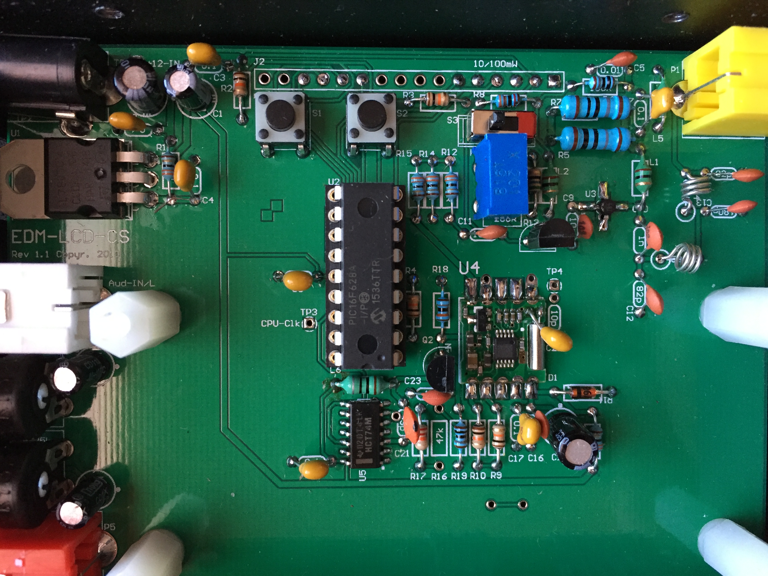
Here's a photo of the circuit board of the EDM for those who are interested:
And also the correct link for the present exact manual for this transmitter (which is basically the same as the one posted). You get the link for the right paperwork when you return to the ordering pages after making payment. Note it says documentation comes with the transitter (it didn't) and it still says you have to install the processor chip (mine was installed already).
http://www.edmdesign.com/docs/EDMLCDCS.pdf
TIB
The power output transistor looks like the dreaded GAL5.
That would be a deal breaker for me as that chip was an issue in the Ramsey. With no harmonics or spurs I assume their using the newer BH1415F chip for the actual FM frequency and the built in limiter like those newer Belkin transmitters use.
NO! that is not the dreaded GAL-5. The GAL -5 is not that shape at all. That is just a surface mount output transister. And if you look closely you will see a coil across the output which looks like it functions as a protection for static voltages. With DC you would see continuity from conductor to ground but with RF at the FM frequencies that coil would have a high impedence, same as my Decade MS100.
But it's still a good idea to make sure you have no sparks jumping off your fingers if you touch the arial.
This model shown is the basic one. There's also an audiophile model with all through hole components and no surface mounts except for the display processor. http://edmdesign.com/features-1.html
Mark
The GAL5 I installed on a FM-100 looked just like that.
The EDM sounds as if it would be a good candidate for leaky cable (radiating cable) if you were planning on wiring up a church, school campus, auditorium or even an apartment complex. The variable RF control is a nice feature even if the settings are a bit weird and it puts me in mind of my Ramsey FM 25 B.
I am able to get pretty low power output by turning the pot almost down to nothing and remain in the expected 200 foot range using just a wire dipole pinned to the wall.
Heck, most of the Ramsey Am/Fm transmitters can be adjusted in the same manner with the exception of the AM-1 and the entry level FM transmitter Ramsey used to sell for $40.
Edit: ok not so much the Ramsey AM's, but the FM's can be adjusted.
Now if i can just convince the gooberment that this is a learning campus and not our house I would string radiating across my yard and fences. lol
Tim thanks for doing these tests and reviews.
Today I received two of the antennas that EDM sells to go with their transmitters, and here's what I can tell you.
When put on the MFJ 259B antenna analyzer they tune up at about 103 MHz. I say "about" because the case of the device it's connected to becomes the other side of the antenna and moving near the case with your hand or another metal object dramatically changes the resonating frequency. The antenna is nothing more than a coiled stiff wire inside the rubber sleeve. The shield/chassis side of the connector connects to nothing. There is 0 continuity between the center pin and outside of the connector. Disassembly confirmed that there's nothing connected to the shield side of the connector. This means that the connector and case of your device make up the other side of the antenna. Changes in this device change the resonant frequency of the antenna. E.G. if I add two extra adapters between the antenna connection and the antenna itself, the frequency drops to 100. If I take about 20 inches of wire and clip it to the case (chassis) of the analyzer the frequency drops further. So obviously the amount of metal that is part of the ground side of the connector (the chassis or case of your transmitter if it's metal) will have a profound effect on what frequency is most efficient when transmitting. The antenna has a built in BNC connector and comes with an adapter to facilitate plugging it into the RCA connector on the transmitter. This gives you about 2 inches of total metal on the"shield" side of the antenna.
I'll post a couple pictures and also update the review posted on my testing website with this antenna information.
TIB
Looking forward to what you find.
Mark