
Did you ever try connecting a single wire between a light bulb and an outlet? Probably not. Did you ever even consider doing that? Probably not, because you learned enough in elementary school science to know it takes two wires to complete an electrical circuit.
The same simple principle applies to radio transmitters. A closed circuit must exist for current to flow between a radio transmitter and an antenna. The current just happens to be high frequency AC instead house power AC, and instead of delivering power to a light bulb, the transmitter is delivering power to something called the "antenna radiation resistance".
When you insert a resistor in series with a light bulb, the bulb gets dim. The same is true for the transmitter/antenna circuit. When you insert a resistance in series with the antenna, the transmitted signal gets weaker. Such an added resistance is called "ground resistance" or "ground loss resistance".
We are well aware that a vertical (a.k.a. monopole) antenna has only one terminal to connect to. So how do we get a closed circuit? Earth ground is the other terminal. All current flowing out of the transmitter antenna terminal must be returned through earth ground to the transmitter ground terminal to achieve a closed circuit. Just as you would never consider connecting a light bulb with one wire, you should never expect a transmitter to work without a second wire to close the circuit. Don't ever believe someone who says they have a vertical antenna that doesn't need a ground connection! Would you believe them if they said they can connect a light bulb to an outlet with one wire?
Only in a perfect world would we expect no resistance to the flow of the return current in the earth. In reality, the earth has a "conductivity" rating that varies dramatically by location. Conductivity is the inverse of resistance, so poor conductivity means high resistance and vice versa. The earth resistance will impede the current flow in the circuit and "dim the bulb".
We can't change the earth conductivity in our transmitter coverage area, but we can strive to minimize the resistance in the path between our transmitter and earth. We can do this by installing a metallic-conductor "ground plane" under our antenna at earth level. This provides a large area for collecting and summing the miniscule ground currents arriving back at each small point. After we minimize transmitter-to-earth connection resistance, we still have the regional earth conductivity to deal with. We can't change the regional earth conductivity, but we can take pride in reducing the resistance to the earth under our transmitter as best we can to make the bulb brighter.
A solid sheet-metal ground plane is overkill. A system of wires (insulated or not) fanning out radially, like spokes of a wheel, from the transmitter laid out on the earth surface, or buried slightly, is practical and will suffice. The standard "broadcast quality" radial system consists of 120 radial wires, equally spaced and each a little over 1/4 wavelength long (1/4 wavelength at 1600 kHz is 154 ft!). Most people are restricted by their property dimensions, so a good, practical installation would consist of the transmitter in the center of the property and radial wires extending to the property boundaries. 12 to 24 radial wires 30 to 50 ft or more long is a decent target to shoot for. In general, It's better to have fewer, longer radials than a whole bunch of shorter radials, but a whole bunch of longer radials is best.
Do a web search for "vertical antenna ground radials". You will find a wealth of information. Persist until you find one that explains everything in terms that you are comfortable with.
Nice article and thanks for posting.
Allow me to add as an example that I have good range results (approximately 1.3 miles listenable on a car radio) with a ground mounted system using 12 X 10 foot long insulated radials. The measured (at the feed point) ground resistance varies with moisture from about 10 to 45 ohms. The loading coil R at RF is 18 ohms which appears in series with the ground resistance.
Neil
I have always had trouble understanding
this. Between you both (Phil and Neil)
- I understand the ground return concept now.
You have also patiently explained it in the past.
My brain finally got it.
Bruce, DOGRADIO
The ARRL Handbook has a nicely written section that refers to: "The Antenna as a Circuit."
Ground radials do not need to be much longer than the antenna is tall. A shortened antenna with loading coils will have a more compact "near field" where the majority of the antenna field is. The ground needs only reach out as far as the near field extends. Field intensity drops off with the square of the distance from the base of the antenna.
WDCX: Thank you for that.. it really cleared up a lot.
Ground radials do not need to be much longer than the antenna is tall.
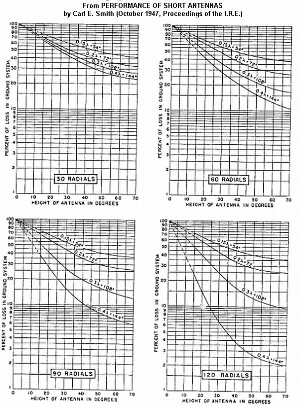
This belief is rather common, but is not supported by careful, physical experiments made over 60 years ago (see graphic below).
A 3-meter vertical is about 6 electrical degrees high at the upper end of the AM broadcast band. It can be seen in the graphs that the percentage of applied power that is lost in the ground system decreases significantly with longer/more numerous radials -- even for 6-deg verticals. The lowest loss shown is for 120 buried radials, each of 0.4 wavelength (144 degrees). In this case the radials are about 24 times longer than the radiator is tall.
(Not that such numbers/lengths of buried radials are possible or practical for most Part 15 AM operators.)
Field intensity drops off with the square of the distance from the base of the antenna.
Both the electric and the magnetic field of a radated wave drop off faster than the inverse distance squared, in the very near-field zone of the antenna (within about 0.16 wavelengths).
Beyond about 1/2-wavelength from a 6-deg vertical, the radiated power is reduced by the inverse distance squared, but the the radiated field intensity reduces directly with the inverse distance (all assuming perfect ground planes).
Thank you for the great info. Even a noob like me could understand alot of what you were saying ! There so many brainy mugs around here my head just might explode! You folks rock !
Mark
Part15.us is the flagship of Part 15 Websites, with the best membership and most professional information.
The forums here at Part 15 are often quoted the next day on the smaller Part 15 websites.
The graphs posted show an interesting trend in that it is the combination of length and number of radials which produces the greatest decrease in the percent of loss in the grounding system. It is a bit difficult to read at 6 degrees height but the loss doesn't appear to change much for the shortest radial length graphed vs. the number of radials. This being said, remember that a change from 95% to 90% loss (not real numbers, just close to those on the graph) represents a doubling of the signal which is not lost power which is a 1.4 times increase in range.
It is never good to extrapolate beyond the data but it seems percentage wise that if the radial length is shortened and the number of radials are fewer that there is not appreciable change in loss because the loss is already near 90% for the shortest and fewest number of radials graphed. But as mentioned above, a change from 90% to 99% would be important. Does anyone know if such data or graphs exist for numbers and lengths typical of part 15 installations?
Neil
Relation between vertical height and radial length
In one of my earlier posts I had some information on the relationship between vertical height and optimum radial lengths. That information was buried in a larger document discussing several other items an was not that easy to find, so I've pulled that discussion out as a separate download. What it shows is that there is a case to be made that, for a given total length of wire, more numerous shorter radials can be helpful on short verticals. At least up to point.
Here is the URL: http://rudys.typepad.com/files/vertical-height-versus-radial-system-1.doc
Does anyone know if such data or graphs exist for numbers and lengths typical of part 15 installations?
I haven't seen any based on measured data, but with a lot of keyboard time they could be generated using NEC-4. The conductivity of the earth in which the radials are buried will be a large factor in the r-f loss of the radial system, along with the number/length of buried wires and the operating frequency.
But referring back to the Carl E Smith graphs posted earlier in this thread (Reply #7), the ground system loss for a 6-degree vertical radiator using 30 x 0.15-wave buried radials is about 95%, and with 120 x 0.4-wave buried radials is about 60%.
The two spreadsheet clips below show the powers radiated with 60% and 95% loss in the r-f ground system. The transmitter power output, antenna radiation resistance, and loading coil loss shown should be close to a typical "Class E" system using a ferrite-core loading coil, at the upper end of the AM broadcast band.
The system with 60% r-f ground loss radiates about 8 times the power of the system with 95% r-f ground loss.
Field intensity (signal strength) varies as the square root of the difference in radiated power. So in this case, the system with 60% ground loss would have a groundwave coverage radius about 2.83 X greater than the system with 95% ground loss.
This gives a general idea of the performance difference between using a relatively good r-f ground connection, and a rather poor one (30 x 0.15-wave buried wires).
The difference would be even greater for fewer than 30 radial wires, and/or radials of shorter lengths.

Thanks, Rich, for the analysis but I have a few comments about this and about the linked data posted by WDCX. Both postings involve radial lengths which are beyond my capability to implement. The "short" radials in Rich's posts are .15 wavelength which is about 90 feet so drawing conclusions from this for radials of lengths of 10 to 20 feet and numbers from 12 to 36, as examples, may not be valid. It does appear that more and longer is better but by how much and is it worth the effort considering the practical limitations?
Another significant contributor to loss is the loading coil RF resistance. Rich cited 18 ohms as being expected using a ferrite core loading coil but I have never seen any data regarding this type of coil loss. My loading coil, wound on a 3" diameter acrylic form with #18 enameled wire close wound, has a measured RF resistance of 18 ohms. Core losses from a ferrite core would be higher than for an air core but this comparison is complicated by the reduced length of wire needed for a ferrite core coil as compared with air core of equal inductance which would tend to reduce the loss, so the two effects work in opposition. Without measured data from a ferrite core coil to compare to my air core coil it remains a question as to which is better to use. I do have a suitably sized toroid core but have yet to wind it for comparison. Perhaps this will be a nice winter project.
Neil
... It does appear that more and longer is better but by how much and is it worth the effort considering the practical limitations? ...
Agree that an accurate understanding of these topics takes a lot of research - both scientific and budgetary.
...Without measured data from a ferrite core coil to compare to my air core coil it remains a question as to which is better to use. ...
Maybe PhilB will make another post in this thread to state the measured loss at resonance of the ferrite-core matching coil included in his AMT5000, for this set of conditions.
Several other manufacturers of Part 15 AM transmitters could do the same, if they wished to.
But even if (for example), such a ferrite-core coil had an r-f resistance of 25 ohms, substituting that value for 18 ohms in my spreadsheet produces a negligible difference in the 8:1 ratio of the radiated powers.
Considering a 25-ohm coil loss with the losses in those two ground system configurations:
For the 60% loss ground, radiated power = 0.1621 mW.
For the 95% loss ground, radiated power = 0.0203 mW.
Ratio of the above power values = 7.985:1
Taking a system where the output power delivered to the loading coil in the antenna system is a constant 85 mW it can be calculated how the radiated power varies as the coil resistance changes.
Pr = I^2*Rr (where Rr is the radiation resistance = 0.12 ohms)
and
I^2 = P/R (where R = antenna system R (neglecting Rr) = Rcoil + Rground and P = total power delivered to the antenna system).
By algebra, Pr = (P/(Rcoil + Rground))*Rr.
Using the most recently measured values of Rground for my system = 24.5 Ohms and measured Rcoil = 18 Ohms:
Pr = (.085/(18 + 24.5))*(.12) = 0.24 mW.
For Rcoil = 25 Ohms:
Pr = (.085/(25 + 24.5))*(.12) = 0.21 mW
Changing only the coil resistance in this example from 18 to 25 Ohms reduces the radiated power from 0.24 mW to 0.21 mW which is a power ratio of 21/24 = 0.88 or a field strength ratio of SQRT(0.88) = 0.93 which supports Rich's conclusion that such a coil resistance change has little practical effect. It would, however, be useful to know if the toroid Rcoil is nearly the assumed 25 ohms.
In my system, the coil is tuned by means of a series connected coil of a few turns mutually coupled to the main coil which allows very fine and precise adjustment. Such would not be the case for a toroid design where taps would be needed producing coarse adjustment but the taps could be combined with a series expandable coil to "trim" the inductance for fine adjustment. Nonetheless, a toroid offers mechanical advantages over the air core coil providing the Rcoil is reasonably close to that of the air core inductor.
Neil