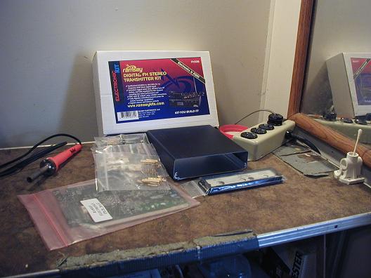
The solder tips arrived at 3:30 PM CST and I already took a photo of the unassembled parts of the FM30B.
Attempts to post the first picture have failed, we'll try again later.
Ramsey supplies a nice inventory checklist for verifying that every part is included, and it's a nice chance to familiarize with all the parts.
As Neil knew, resistor color coding can mean trouble, and checklist part #3 is a resistor that needs to be red-violet-brown (270 ohm), but I find only what appears to be red-brown-brown (210 ohm).
The question arises whether my CFL light bulb is unable to show violet, or perhaps my vision lacks violet recognition.
What we'll do is take a meter reading to detect what the resistor actually is.
Ready to Start earlier today
Sometimes violet can look brown under certain light....check with multimeter to varify. Remember 10% tolerence so may not be right on.
Mark
Caps marked with a 3 digit number generally follow the convention that the first two numbers are the first two digits and the third number is the number of trailing zeros. The value is in pF, e.g. 472 would be 47 with two trailing zeros or 4700 pF. Your part labeled 100 is probably 10 with no trailing zeros or 10 pF.
Letters are used for voltage rating and temp coeff.
A search on the subject will yield better explanations than this one.
Neil
Most better multitesters measure capacitance from very small picofarad values to about 50 microfarads. Measure to be sure it's the right value. Remember the 10 or 20% plus or minus tolerance.
Mark
When I built my AMT-3000 I had to
test all of the resistors with a meter.
Carl, this is exciting for me, and probably
for all the rest of us, too.
Good luck!
Brooce, WLP
Considering that Carl is 115 years old I am proud of him for this project.
I'm older than I thought.
You folks have reminded me that I have a capacitor checker over there in one of those boxes.
Today's the day to fish it out and do some capacitor tests.
I ordered 3 new solder tips, but they come in 2-packs, so I have 6.
Soon as the FM30B is finished and tested I'm heading downstairs to the other workbench to complete the Big Talker Shortwave transmitter and get that going at 13.560 MHz.
Soldering has begun and all the IC (integrated circuit) chips are installed.
See?

As the political campaign ads often say: "I'm Barry Sallade, and I approve this message"
Breathing solder smoke requires a breather once in awhile, and I'm happy to report that many resistors and capacitors have now been installed in the FM30B.
After some cheese and soup we'll go back to work.
You are welcome to wait over there by the SSTran AMT5000.
Carl, pace yourself....do it too fast and you can make a mistake and have a hell of a time finding it.
When I solder I have a small fan beside me on low to blow the solder smoke away so doesn't rise straight up to breath it.
The flux in the solder even if it's unleaded is not good to breath! Can do damage!
Please.....get a fan on the table so you don't breath it.
One solder tip should last for the whole project and indefinitely for that matter.
Keep a wet sponge with you and keep it tinned and shinny by lightly wiping it with the wet sponge every few solders.
Mark
Carl Blare is pacing himself and looking about for a small fan, not rushing, taking it easy, these two FM30Bs will be done soon. Uh, one FM30B... had double-vision there for a minute.
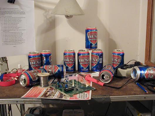
I see you are building an antenna also.
Is it hard to solder cans of Best Premium
together?
Keep going, slowly, if you have to.
Thanks for the photos.
Brooce, WLP
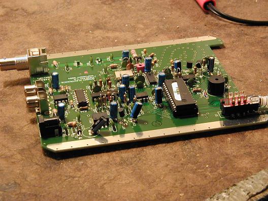
The Main Board of the Ramsey FM30B is now complete and on display so you can help by looking for mistakes.
The only mistake I knew about was late last night when I realized I'd inserted a resistor in a capacitor slot. That was my clue to stop work for the day.