
Now that I've figured out my Talking House is not defying the laws of physics and only putting out a 6 volt peak-peak signal (across a 50 ohm load)....
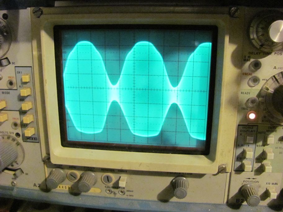
I think RFB might be on to something about a modulation problem...Here's is the output voltage across the dummy load when modulated by a 440 hz sine wave from a signal generator. I'm concerned about the fact that the bottom part of the envelope is squashed and asymetrical from the positive part of the envelope.
The asymmetry was apparent at various audio frequencies and at varying modulation depths.
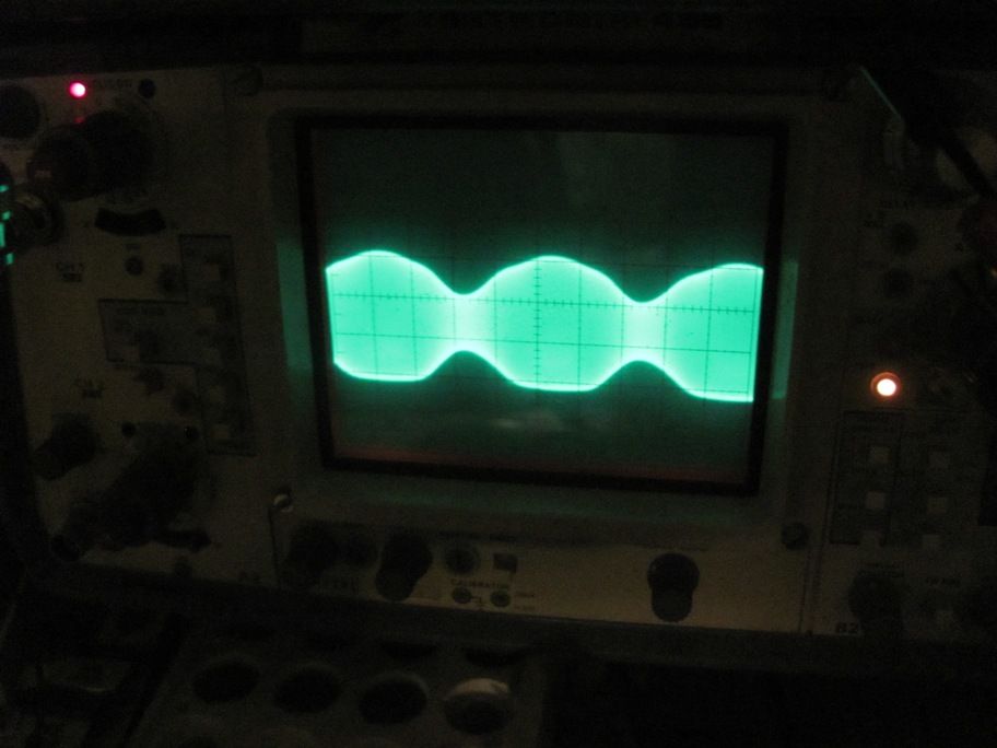
Here's the same setup w/ less modulation (the bottoms are still flattned out):
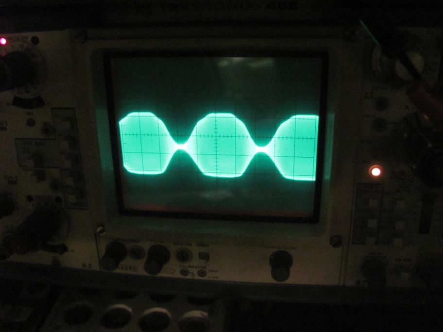
here is is over-modulated:
If the distortion is the same at low and high audio levels which it appears to be in the photos then I suspect the problem is in the audio circuitry. A DC bias problem in the final stage usually affects the modulation waveform mostly at high audio levels. Also, aren't the second and third waveforms the same?
Since you know this is distorted then you know how a proper waveform appears but just for reference here's a photo of the audio and RF envelope from one of my transmitters which shows that even simple transmitter circuits can perform well.
Neil

If you get to the point where you want to probe around inside the transmitter one very nice way to view the transmitter final stage operation is the trapezoidal display. It is produced by setting the scope to X-Y mode with the modulating signal(audio) on the X axis and the RF output on the Y axis. The audio signal is the modulator output signal at the final RF amplifier.
A good deal of information is contained in the display such as linearity (the top and bottom lines should be straight), phase shift (there should be no looping of the pattern), and modulation percent (calculated by taking the high side height = A and the low side height = B and M = (A-B)/(A+B) x 100%).
Here's a photo of such a display showing slight overmodulation as indicated by the straight line on the right side of the trapezoid. At 100% modulation the right end of the pattern is a sharp point.
This is how I set my audio levels for correct modulation.
Neil

here's the correct over-modulated pic:
I don't believe the audio is over-driven. It seems to have the same squashed bottoms regardless of audio level.
Here is a possibility. You said the voltage across 50 ohms was 6V p-p. That was for the unmodulated carrier. Correct?
In your first picture above, , I can't see the switch, but I'm guessing it is set for 2V per division. If that's the case, then even in the first picture, the modulation is well over 100%. I think the peaks at the bottom of the screen are flattened at 6 volts below the zero-mod point due to over modulation. With heavy over modulation, the asymmetry is fairly meaningless because it depends on the bias point of the modulator circuit.
You should try reducing the audio level substantially to see if that flattening goes away.
"I can't see the switch, but I'm guessing it is set for 2V per division."
Phil,
I', pretty sure the switch was set at 1 volt per division in the photo you reference. We were cranking the audio (sine wave) level up and down on the signal generator and the total peak to peak voltage only increased slightly at we increased the audio level. The peak to peak voltage never exceeded 7 volts no matter how much we drove it.
EDIT: here's the overmodulated pic. still a litle over 6 Vpp.
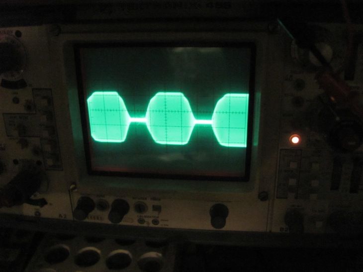
Here's WAY over-modulated, still 6 VPP...
OK, guess you shot down my last theory.
Here's an easy thing that is worth trying before you dig into the circuit.
To view the modulated RF waveform when the transmitter has its final tuning circuit connected and properly tuned you can easily sample the RF output waveform on the antenna wire with the transmitter set for internal auto-tuning.
Clip your Tektronix scope probe to the transmitter antenna wire over top of the wire insulation. This will give you enough capacitive coupling to see the RF waveform without disturbing the tuning significantly (the auto-tune should kick in to compensate for any small increase in capacitance). Clip the probe ground lead to the transmitter chassis. Adjust the volts/div knob to get a good size waveform. An unmodulated carrier should display as an almost perfect sine wave at the operating frequency. Whatever modulated waveform you get will be the same as what is actually going out on the air.
I'm thinking that you may see a waveform more like Neil's photos because the transmitter is operating with a tuned antenna load. If you still see a bad modulated waveform similar to what you see across the resistor, then a problem does likely exist inside the transmitter.
On the other hand, it is quite possible the distorted waveform you see across the resistor may just be an artifact of operating with an untuned resistive load, which isn't the way the transmitter operates when the internal or external tuning circuits are connected.
I have experienced the squashed looking waveform when the antenna goes out of tune usually due to damp weather. Perhaps not quite as noticeable but still reduced in max amplitude.
I always attributed it to the antenna impedance being to low. As such I'm guessing the Talking House internal power limiting causes this.
Thanks Phil, I'll try hooking the scope up to the wire antenna when I get a chance. I did try clipping the scope probe (directly) to the wire antenna output but the auto-tune wouldn't calibrate. I'll try hooking it to the wire insulation.
Right now, I'm trying to set up this TH to test different antennas, so I was figuring on using the 50 ohm dummy load as a baseline and getting into the black art of antenna matching. I was really hoping for some poor man's way to test SWR without buying expensive test equipment.
The output of that unit is designed with a toroid coupling transformer, which isolates it pretty darn well from both the internal ATU and external ATU. However a severe mis-match can cause a distorted or lop sided envelope, but that mis-match would have to be pretty darn severe to affect it as being suggested by a few.
What you might try is a variable resistive load and observe the envelope waveform during adjustment of that variable resistive load. If it is a loading issue, that envelope won't just flatten out on the bottom side. It will vary from the bottom to the top lobes and the adjustment of the variable resistive load would have to swing quite wide from its resonant point.
I still think you got a modulator problem sending a positive shifted DC voltage from over-biasing of the modulator transistor from the op amp IC, sending more DC voltage to those two finals as well as their biasing which comes from the same voltage line as fed to the collector of the top final transistor through a resistor. This is the ONLY way that thing is going to output more RF than what it should be doing, and also make that envelope lop sided to the positive.
All of this is of course assuming you are using the supplied AC adapter power supply that comes with those TH units? Reason is that the modulator transistor is fed 18VDC directly from the 18VDC input with a couple of bypassing caps along the way, but it is the same 18VDC from the power supply. Everything else in that transmitter is fed B+ from an array of voltage regulators located on the far left of the unit (looking at unit inside as front unit faces you).
You could also check the B+ going to the op amp IC and see if it's B+ is correct because if it is more than 12VDC, that can cause it to output a positive voltage on it's output..which would also cause the positive lop sided envelope and probably swing with the audio being fed through it. However I think you got a flaky op amp IC or quite possibly some varying DC voltage going into it's input due to a bad C301 capacitor passing DC instead of blocking it. However that part of the circuit would have to be over driven pretty darn hard, which audio to C301 comes from an internal AGC circuit that is in front of that C301 path, and both the internal digital recording audio and external audio inputs go through that AGC circuit. If it is damaged in some way, C301 would still block any off-shifting DC from passing through it.
RFB
Also, that TH unit won't auto-tune with it's internal ATU without the simple wire antenna connected. It is designed to only function and tune correctly with that wire and nothing else. You can loosely couple to sample that signal from the wire antenna by placing the scope probe nearby or clamped to the wire itself, making sure it is insulated so that there is no electrical contact between the probe and wire antenna. That should be more than adequate to measure for that envelope.
Without the external ATU to properly load and tune in the external antenna mode, you won't get a proper measurement either. But you might try a 50 or 75 ohm non-inductive resistor on the output connector and switch to external antenna mode and loosely couple the scope probe to that load resistor, again more than adequate to measure and see the envelope.
RFB
Thanks for the detailed response. Yes, I am using the factory supplied TH wall wart. Also, all of my testing was using the External Antenna jack through a 50 ohm non-wire-wound resistor.
I was going to try to recheck the modulation envelope using various resistances as a dummy load, but I must have left my audio cable over at a friend's house (UGH!%$#).
I printed out the Patent Application Schematic for the TH to try to follow your comments but unfortunately I can't really read the text. I've been going back to the basics over the past 2 weeks and reading my Understanding Amateur Radio book to try to understand modulation, resonance, etc, and it's slowly sinking in but I still ahve a ways to go to understand everything. A schematic for the TH would certainly simplify things.
As a side note, this unit is a $50 TH II model that I'm just using to test antennas with, so if I ruin it, it's no big deal. The TH-5 unit is at another friend's house that works (and sounds) MUCH better.
"I printed out the Patent Application Schematic for the TH to try to follow your comments but unfortunately I can't really read the text."
The patent schematic is a very poor quality PDF and although the component designations and values are difficult to see, the actual circuit map is clear enough to see how things are working in the unit.
That PDF schematic..and an actual schematic collected some months ago are identical with the exception the actual schematic is crisp and clear to see the circuit map and part values/designations.
Contact...3-2-1..LIFTOFF! 😉
RFB