
Audio sent via internet is possible, but probably deserves its own thread. I'll start one and give my (as yet incomplete) thoughts.
Northernlightsmedia, if you are concerned about "being legal," then the plots at 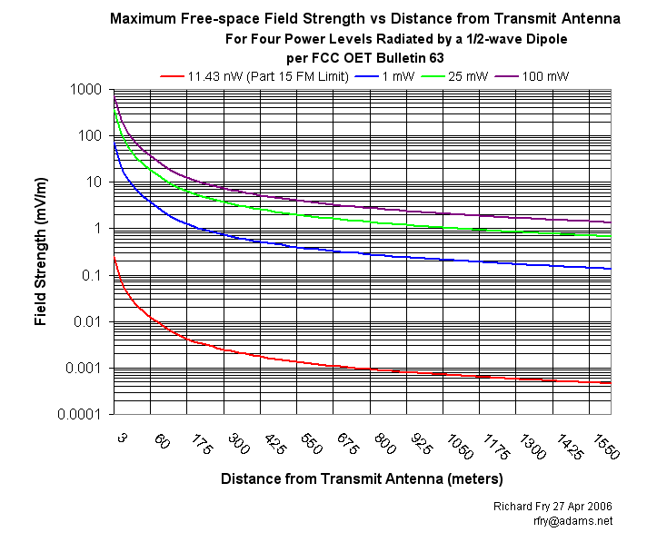 will show what coverage you can expect for a clear radio path (the red curve), plus several for other conditions that are not legal.
FWIW, it takes very little power radiated even by a simple dipole antenna to produce the FCC maximum field strength for Part 15 FM. There are examples of FCC actions for FM field strengths that were less than shown at the distances in those plots, so using the powers that you have stated will just increase the chance of discovery.
//
Reference your "I got the boss" post. I don't know what they were thinking when they connected the carrier current to the outside light power string since the idea of carrier current is to provide a signal right next to the receivers obviating the need for a strong radiated signal. Maybe the target audience was those who sat on the bench beneath the lamp. Since it is abandoned, it is now moot.
The SSTRAN or Rangemaster approach is worth a try. Maybe start with the SSTRAN because of the $$$ and experiment. I think you will find issues with building penetration and electrical noise which will really limit your range, but experimentation is the only way to know for sure.
Neil
The daytime range of an AM station does not increase as much as the square root of the power ratio. This is because of absorption of the groundwave by the earth. The square root rule would only apply if the earth were a good conductor. In urban areas, the earth is usually a poor conductor, and the groundwave absorption is high. The high end of the AM broadcast band has much more groundwave absorption than the low end. Most Part 15 AM operators operate near the high end of the band to maximize antenna efficiency.
Prof. Bill Everitt, author of "Communication Engineering," McGraw-Hill, 1937, gave a rough rule of thumb that the range of an AM station increases as the fourth root (square root done twice) of the ratio of the power increase. Dr. Everitt was Professor of E.E. at U. of Illinois, Urbana, when I was a student in the Sixties. The rule gives a range increase of only 1.78 for a tenfold power increase. To get a range increase of 3.16, a power ratio of 100 is needed. This is ten watts! One of the contributors to this topic, Jim B, expresses dissatisfaction with increasing power from 100 mW to 1 W. Clearly, a power increase of this amount does not bring happiness.
We are talking about a 100mW range of 1 to 3 miles, which is not very likely unless the antenna is much longer than the 3 meters allowed by the rules. For an antenna that is legal, the range may be so short that there is hardly any groundwave absorption at all. Even in that case, the square root rule does not apply. This is because, at a short distance from the antenna, the near field intensity decreases rapidly with distance.
For an antenna that is legal, the range may be so short that there is hardly any groundwave absorption at all. Even in that case, the square root rule does not apply. This is because, at a short distance from the antenna, the near field intensity decreases rapidly with distance.
True in general -- fields in the reactive region surrounding a radiator do change at a rate greater than the inverse distance from the radiator. However for a very short radiator such as used in Part 15 AM that reactive region extends only to a distance of lambda/2*pi -- which for 1610 kHz is a distance of about 97 feet.* This is well short of the distances people consider desirable for "community broadcasting." Beyond that range the inverse distance rule applies for short paths, after which ground losses accumulate to reduce them even further. Note that both of these factors are independent of the actual power radiated by the antenna.
Using the FCC's propagation curves for 1610 kHz and a ground conductivity of 8 mS/m (rather average), here is the result of increasing a Part 15 AM tx power output from 80 mW to 1 watt, using the same 3-m, ground-mounted radiator:
Tx Output Power > Distance to 2 mV/m contour
80 mW > 468 feet
1 watt > 1,478 feet
A field of 2 mV/m should provide good service to a cheap indoor radio.
So Neil's 3.16 factor applies quite well here, as well as your observation that the actual ground conductivity makes little difference over very short MW paths.
* "Antenna Theory, Analysis and Design," Balanis, 2nd ed, section 2.2.4
//
Ermi and Rich,
Thank you both for refining my rough estimate of range increase seen by increasing the power by a factor of 10 for AM. My factor, 3.16, is simply the square root of the power ratio which gives the field strength ratio. Assuming no ground losses and a linear decrease with distance for field strength connects this number to distance.
So, it appears we have two numbers which probably give the boundaries of what to expect: range increase from 1.78 to 3.16.
Another way to look at this is in terms of potential listening units (residences or people). Assuming a homogeneous distribution of listening units per unit area, then the ratio of listening units would be proportional to the square of the distances. Normalizing the math, if 100 mW. gives 1 listening unit then 1 Watt would give from 3.16 to 10 listening units by covering 3.16 to 10 times the area.
I don't know if this is how the pros figure potential listeners but it seems reasonable as a rough estimate.
Neil
Thank you for your response to my contribution. I agree completely with your conclusions. The nit-picking comments that follow do not detract at all from the correctness of the points you have made.
8mS/m is pretty good earth conductivity. A tenth of that is not uncommon where part 15 AM transmitters are used (in concrete jungles, for example).
To get 2mV/m field strength at 468 feet requires about 1 mW of radiated power, even without any groundwave losses. The efficiency of the antenna and coupling circuits would have to be slightly over 1%. Such a high efficiency can't be obtained with a 3 m whip over ground if transmitting the full audio bandwidth is desired. The FCC frowns on such antenna enhancements as capacitive hats, large antenna diameter, and ground radials. Also, the coupling circuit causes more inefficiency than a lot of designers realize. Most people know that circuit resistances cause power loss, but so do circuit capacitances.
Even if the system were so good that the full 100mW were transformed into radiated power, it would not be possible to produce a field strength that is quite as high as 2mV/ meter at one mile. So, the notion of a 1 to 3 mile range is a dream, especially if the signal quality of licensed broadcast stations is expected.
Ermi,
Your reply is appreciated and I don't mean to pick nits either but could you please provide a bit more information?
The FCC frowns on such antenna enhancements as capacitive hats, large antenna diameter, and ground radials.
I wasn't aware of this. If the antenna system is within the 3 meter limit it would seem that it is compliant with part 15. The rules also allow for a ground connection which limits the antenna and ground lead total length but do not specify what the ground is (such as buried radials). Perhaps you know of some situations where the FCC objected. Could you elaborate?
You wrote:
Most people know that circuit resistances cause power loss, but so do circuit capacitances.
Since theoretically capacitances and inductances only store energy which is returned to the circuit, I wonder if you are referencing some secondary effect such as mismatches or coupling to resistive effects due to the capacitance. It is pretty well understood that the effective resistance (and not the inductance) of a loading coil contributes to power loss but it is small compared to the ground losses of an antenna system with radials so heroic efforts such as silver plating or large diameter wire for these coils seem not to be worth the effort.
Thanks,
Neil
The nit-picking comments that follow do not detract at all from the correctness of the points you have made. ... To get 2mV/m field strength at 468 feet requires about 1 mW of radiated power, even without any groundwave losses. The efficiency of the antenna and coupling circuits would have to be slightly over 1%. Such a high efficiency can't be obtained with a 3 m whip over ground if transmitting the full audio bandwidth is desired.[/quote
In the belief that nit-picking shouldn't equate to supplying data that differs from another's post, it should be noted that a ~3-meter x 1/2-inch OD copper radiator on 1610 kHz together with a coil loss of 2 ohms and a ground loss of 8.65 ohms comprise a Part 15 AM radiation system with about 1% efficiency.
The VSWR bandwidth of this system certainly is adequate to provide the r-f/audio frequency response that most modern AM receivers are capable of using. Here is a plot of it: 
The ground loss value in my example represents an r-f ground at the high-quality end of those used in most Part 15 AM installations. The goal was to show about the best performance possible, to see if it supported the claims of 1-3 mile coverage for a legal Part 15 AM setup.
Even if the system were so good that the full 100mW were transformed into radiated power, it would not be possible to produce a field strength that is quite as high as 2mV/ meter at one mile. So, the notion of a 1 to 3 mile range is a dream, especially if the signal quality of licensed broadcast stations is expected.
The 2 mV/m contour was chosen because it is a signal that an average, casual radio listener using a cheap indoor radio in a suburban area would notice when tuning across the dial, and could listen to with minimal noise (lacking interference).
But that's not the coverage limit for those with very good radios and clear paths, a high interest in listening to/promoting the station, and/or Part 15 AM stations using elevated radiating structures (~3-m whip plus the radiating ground lead and radiating ground conductor/flag pole/tower/billboard) that together exceed the 3-m limit for the radiator given in 15.219.
//
OK, so how does one optimize a shortened 3m base loaded antenna to be more efficient? Is the diameter of the tuning coil an issue, or is it just a matter of using a larger gauge wire to wind the coil? Example antenna design being the one on the SStran web site. Assuming that money is no object, can an antenna like this be pushed to much higher than 1% (like 10% or more) assuming a "normal" "average" ground?
Greg,
That is a good question. I have taken some information from what I have read and thought it might help to put it together in one place, especially for the new readers here.
Many times engineering solutions are a balance of what is practical guided by theory rather than what is ideal. That's the approach I will take here. I am referring to a base loaded 3m antenna with buried ground radials and am assuming that the radiator capacitive reactance seen by the transmitter is cancelled by the loading coil inductance which is easy to do in a practical sense.
To increase efficiency, we need to lower the losses by:
1. Lower the coil loss by using large wire to decrease its resistance at the operating frequency. Here is where we get beyond practical gain since this resistance is small compared to the ground resistance which causes the major loss in the system and a reasonable reduction in coil resistance will not have a major effect on the overall efficiency. If we keep it below 2 ohms or so then it is not a big factor in efficiency. #12 to #18 wire will suffice.
2. Coil form factor. Most authors of amateur radio articles on the subject recommend a small length to diameter ratio which leads to a coil that is short with large diameter such as the one recommended on the SSTRAN site. I have seen recommendations of 1:1 but I don't see the advantage of this over the SSTRAN recommended coil.
3. Reduce ground loss. I assume that we don't have control over ground conductivity (though I recall a post where someone described a system to keep the soil wet) so what is left to control is the number and length of the radials we install. Again, we are limited by practicality but we know which direction to go with this.
4. Radiator diameter. This affects the bandwidth of the antenna system. We need it wide enough to radiate the sidebands and Rich's graphs linked in his earlier post show that a 1/2" or greater diameter radiator will suffice.
Here are some of my thoughts where improvement is possible:
If someone builds an antenna per the SSTRAN site instructions, he will have an effective, practical antenna which could be improved by more and longer ground radials but is the improvement worth the effort? I don't know.
I would look instead at the efficiency of the part15 AM transmitters. Theoretically, a Class C amplifier can have 100% efficiency but practically it is closer to 70% based on my experience building VHF amplifiers. I measured the efficiency of my Ramsey AM-25 in a bench test with several different load resistances. The maximum efficiency was 31% with a load of 24.3 ohms. With a legal input of 100 mW. this gives an output to feed the antenna of 31 mW. (though the actual powers produced in my test were different). If this circuit could be improved to a 70% efficiency, it could increase the range by 40% legally. I do not intend to be critical of the Ramsey design but rather I am just reporting what I measured. I have no data for the SSTRAN AMT-3000 or the Hamilton Rangemaster (R)..
Hope this helps and gives some ideas for discussion or experiments.
Neil
OK, so how does one optimize a shortened 3m base loaded antenna to be more efficient? Is the diameter of the tuning coil an issue, or is it just a matter of using a larger gauge wire to wind the coil? .... Assuming that money is no object, can an antenna like this be pushed to much higher than 1% (like 10% or more) assuming a "normal" "average" ground?
The r-f resistance of a "broadcast quality" ground system of 120 buried radials, each at least 1/4-wave long is about 2 ohms. So if the Part 15 coil also has a resistance of 2 ohms, then even at the top of the broadcast band the best antenna system efficiency possible will be around 2-1/2 %. Lower frequencies are not even that good.
But the ground system installed for most Part 15 AM is far worse than this - possibly as high as 20 or 25 ohms. A 20 ohm ground used with the above example would yield an antenna system efficiency of about 0.45%.
Note that ground resistance is not the DC resistance of the conductors leading to some kind of buried "ground" such as a water pipe or an arrangement of buried ground rods near the antenna. It is the resistance to the flow of r-f current from the earth in a radius of ~1/2-wavelength from the antenna back into the ground terminal of the transmitter/antenna system. Those r-f currents have substantial loss if they cannot be collected by the radial system without traveling more than a short distance before they reach one or more of the radials.
The r-f ground resistance is in series with the r-f current flowing on the 3-meter radiator. That is why it is so important to minimize that resistance.
//
OK, so it really comes down to the only real gains are to be made with a system of ground conductors (ground plane) which is kind of what I thought. Just wanted to make sure before I commit to buying materials. I still need to push to build things, but the season for putting up the antenna is drawing very near now, and I really want to have things built before then and ready to go.
BTW, if people are looking for copper pipe Grainger carries 5 and 10 foot lengths of type L rigid copper for about half the price of Home Depot. That shaves about $20 off the price of the antenna on the SStran web site.
OK, so here is another question... Does the height above the ground plane of the shortened 3m whip play any role in the efficiency? Just wondering if it would be pratical to mount the antenna at 1/2 or 1/4 wavelength above the ground.
and would someone check my math here:
At 1640 Khz the 1/2 wavelength would be 91.46 meters or approximately 300 feet
Looks like I might be able to get almost 1/8 wavelength above ground (dirt) but the building structural steel is going to be much closer, and I don't know what kind of RF ground plane it is going to give. I do know that each piece of vertical steel has been bonded to a ground rod, and the tower has been bonded to the steel to provide protection from lightning. The building will give about 1/4 wavelength is a couple of directions, so I might get a decent range should the building work as an effective ground plane. If only it had a giant metal roof... (which it actually might have under the water proof material)