

"Does this mean the transmission line from the TH to the ATU radiates? I don't know but this suggests that it could."
I did similar tests to my outdoor 3m system, though it sits about 1 meter off the ground on a short fence pole and a ground rod at the bottom connected to the mount pole. The 3m system is a simple loading coil feeding a 1/2 inch diameter copper pipe 9 feet long. The loading coil is 3 inches diamater, 80 turns tapped at 70th turn with the variable cap. All fed by a standard CATV cable. Like Neil's reason, initial setup of the system is severely affected when in close proximity.
Connecting to a TH V5 unit, with the ground slug of the input coax connector connected to the mounting pole, or not, my plain ol field strength meter, a cheap CB jobber, picked up radiation from the coax shield when placed about 3 inches from the line, and pegged it when placed right on the coax.
RFB
Here is Gerrett's email: [email protected]
It did not show up when I did the cut and paste.
I tend to take people at their word. As such when Gerrett told me the FCC acceptance does not consider the coax shield as part of a ground connection I believe him. And now that I look over the text, I'm the one that said that to him and he did not dispute it.
His final Ipad reply was simply giving me permission to post his replies for others to see.
I do agree this cannot be put to rest until hard data is actually in hand. However, I still have that warm fuzzy feeling of security.
So, contact Gerrett and let's see what his story is to a different individual.
Radio8Z, you mentioned using a transmission line for test purposes, and I wonder if you calculated the RF loss, if any, caused by that transmission line.
And I quote you on another matter:
"I have a large loop antenna with a FS meter attached which I built and using this determined that there was a relatively strong RF field coming from the transmission line."
Simple question. Did you build the loop and FS meter, or just one of the two?
rich linked a caveat published in the ATU Manual regarding the possibility that a ground connected from the ATU Unit to earth might exceed the part 15 limits, and while that does not address the question of the 300-foot transmission line, it raises valid questions.
1. What is there to ground out at the ATU? We usually speak in terms of grounding the transmitter.
2. I thought there was a second question, but now I'm confused.
The radiated power of the antenna might have been affected by the apparent radiation from the transmission line but there was no difference in the field strength reading with the transmission line in use and with the transmitter mounted at the base of the antenna. There are several possible explanations for this but the simplest is that the total field at the test receiver antenna was the sum of the antenna field and the transmission line field.
The loop antenna and field strength meter were built by me. The meter circuit is attached directly to the loop antenna and consists of a 50 uA meter, a 1N34 diode, and a bypass cap. The meter is mounted on the frame for the loop. Here's a photo.

Neil
Radio8Z your RF Field Strength Meter apparatus is a glorious and beautiful low power instrument, and the way you have it set against a lovely grotto wall seems religious to me.
I think I have found faith at last!
carl wrote: What is there to ground out at the ATU? We usually speak in terms of grounding the transmitter.
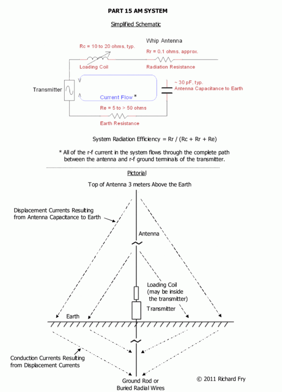
For best antenna system efficiency, a whip (monopole) antenna needs an external path between the earth and the antenna system for the r-f current radiated into the earth, near the whip.
That path can be provided by the shield of the coax between the transmitter and ATU, via a connection through the transmitter to a "power line ground." However that is usually a high-resistance path for r-f current, and losses can be very high.
A separate wire from the ATU to a good r-f ground such as buried radials around the base of the antenna can have less loss than the power line ground, and improve the performance of the system. But if the ATU and whip are installed on an elevated mount, this can lead to conflict with §15.219(b).
Here is a link to a simple schematic showing these current paths.
Someone needs to try and file an FOIA request for the THII/iAM certification docs. i never tried. i only tried for the hamilton rangemaster.
if someone does not beat me to it i'll do it in time but right now i am emotionally burned out over many things.
Yeah it's ironic that we would have to file an FOIA request for something that is supposed to be public record to begin with.
RFB
"A separate wire from the ATU to a good r-f ground such as buried radials around the base of the antenna can have less loss than the power line ground, and improve the performance of the system. But if the ATU and whip are installed on an elevated mount, this can lead to conflict with §15.219(b)."
Very true, especially considering the ATU ground for the whip is the same ground potential (same ground) as the coax ground, which would also mean its the same ground as the power supply cord's ground, as well as the audio grounds.
The schematics provide the validation to that.
RFB
I specifically asked Gerrett about the coax shield versus the grounding point of the ATU. He stated that the coax shield was not a factor but any wire attached to the grounding point does.
I emailed him last evening and gave him a link to this thread so he can check out the discussion.
Mr. Conover of Radio Systems has sent a follow up regarding the ATU:
==============================================================
Bob,
The patent for the TH-5 tuning unit includes wording which goes directly to the Part 15 issue. "The external ATU is the final output state to the transmitter when selected". This patent was included in the Part 15 filing. In other words, this means the coax cable between the TH-5 and the ATU is NOT transmission line. The antenna itself is 96", so care must be made to ensure that the ground lead doesn't put the antenna system over 3 meters in length.
--------------------------------------------------
Gerrett H. A. Conover
Vice President, Radio Systems
601 Heron Drive
Logan Twp, NJ 08085
856-467-8000 Voice
856-467-3044 Fax
856-803-1060 Direct
==============================================================
As stated, adding the separate ground wire could be a problem but as recently reported a roof top install with separate ground was accepted by the FCC.
This being the case the extra ground may be a crap shoot so I'll go with grounding the coax inline lightning protector at the structure entrance in lieu of a separate ground.
According to a previous post in this thread, "The patent for the TH-5 tuning unit includes wording which goes directly to the Part 15 issue. The external ATU is the final output state [probably -- stage] to the transmitter when selected. This patent was included in the Part 15 filing. In other words, this means the coax cable between the TH-5 and the ATU is NOT transmission line. ..."
Two fundamental issues flow from the post of the originator of that quote.
1. The conventional definition of an r-f stage applies to an active device/circuit, i.e., one producing power gain between its input waveform and its output waveform -- IOW, an amplifier.
Apparently such a "Part 15" remote ATU does not perform that function. Rather it adds loss to the incoming waveform as a result of the r-f resistance of its loading coil and other components, even when that coil is critically tuned to system resonance.
That circumstance/result likely does not meet the classic definition or use of the term "r-f stage."
2. A well-shielded coaxial cable always functions essentially as a transmission line. After all, that is its purpose.
Attempting to define such a cable as anything else, and exempt from FCC §15.219(b) may lead to eventual problems with the FCC.
I would argue that an "active" amplifier can also be turned down so as to deliberately ad loss to an RF signal. In this case it would be on a par with a lossy loading coil, with regard to signal loss.
On that same point, a "passive" component such as a step-up transformer can increase a signal level passing through it, again rivaling what an amplifier can do.
But I do agree that a transmission line as a transport pipe for RF is a transmission line. I think what we have here is a transmission line PRIOR to the final RF stage, which is not the same as a transmission line following the final RF stage.
ADDENDUM:
I also submit the function of the loading coil, bringing the antenna to resonance, is a function akin to amplification.
Only way I would be convinced of everything said above by Mr. Conover is if Mr. Conover or the FCC makes the certification documentation available so we can see for ourselves exactly how the units are indeed certified with what and if that is not part of the antenna and this is actually the final stage.
Mr. Conover, if your reading this thread, then I ask that you provide a copy of that OET certification documentation which will have a description, pictures of the test setup, a pictorial drawing (block diagram) of the test setup, measured results as declared in the DUT's specifications.
Now if there is no conflict between what you say in email to MRAM and gets posted here versus that certification documentation, then there should be no reason why that information would not be made available to anyone asking for it.
All other Part 15 devices that are certified have a record of that OET certification in a database. All except YOUR unit, and one other.
Interesting.
So..do we continue this dance around the point garbage or get to the one thing that will solve and put to rest this question of elevated ATU's at 300 feet being ok under 15.219, or even 100 feet, or even 25 feet.
The ball is in your court Mr. Conover.
RFB
I submit to you that you now have the email and telephone number for Mr. Conover.
Rather than assume he is reading the posts here, why not just call or email him yourself. He seems responsive enough to me.
It's obvious that someone of our forum has contacted Mr. Conover to inform him of the posting of their proprietary information here. He apparently learned of this after I posted his contact info here for all to see.
If I were Mr. Conover I would be offended by comments suggesting he is falsifying information.
If he publicly states the patent info included for certification identifies the coax as interstage coupling (my words) and not antenna lead wire (which it is not-the antenna connects directly to the loading coil in the box) he would most certainly open himself to litigation if not true.
I sincerely believe this not to be the case.