
RE: "These formulas are designed for higher power transmitters, not part 15. For example my part 15 has no loading coil. The efficiency is higher then he mentions. So his calculations are not that useful I think”
My public, quotable comments to that above text clip are:
1.) The formulas contained in the NEC4.2 software used to create the data for the graphic following below are valid and accurate at all power levels, including the range of nanowatts to megawatts. To state otherwise provides incorrect and misleading information. Anyone wishing to verify this is free to do so by their own research, or by contacting Gerald Burke or Andrew Poggio of the Lawrence Livermore National Laboratory in California, the co-authors of that software.
2.) A Hamilton AM1000 Rangemaster(TM) transmitter includes an internal loading coil wound on a ferrite core. That coil cannot have zero resistance to the r-f current flowing through it, and does contribute to the losses present in the load impedance of the transmitter output signal — which reduces the power output (efficiency) of all transmit systems using that transmitter. This copper-wire coil is wound on a circular core, and is visible at the upper left of the transmitter enclosure shown in the "tuning" video currently linked at "https://www.youtube.com/watch?v=dennCHkoQ0w"
3.) A rather optimistic estimate of 15 ohms was included for the loss of an internal loading coil at system resonance, as the third item from the bottom of the list showing the complete system description that was analyzed in my graphic below.
In my engineering opinion, the chart below shows about the maximum performance to be expected for a Part 15 AM system meeting FCC §15.219(a) and §15.219(b), for the complete conditions stated there.
Of course operators are free to install any system configuration they wish, at their own risk. However, if its performance significantly exceeds that shown in the chart below, it might be more likely to receive a field inspection from the FCC — even if that installation configuration was/is suggested or endorsed by the manufacturer or agents of the transmitter that system uses.
The graphic referred to above is shown as the next post in this thread.
Graphic for the opening post in this thread:
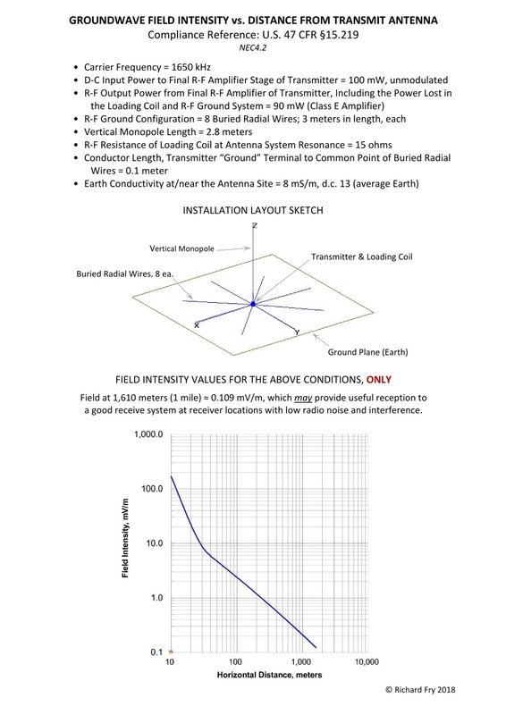
Rich, is the change in slope on the graph at D = 30 meters due to the transition out of the near field into the far field?
In addition, my installation is reasonably described by Rich's model for this calculation and I know this because I have measured the loading coil RF resistance and ground system RF resistance. The physical description closely matches that of my installation.
The range I observed by driving in three directions away from the transmitter site is approximately 1 mile in each direction which is in agreement with Rich's predicted range. I have no way of knowing the sensitivity nor directional receiving pattern for my vehicle radio so I cannot estimate any field strengths, only listenable range.
One interesting and repeatable observation is while traveling away to the south my signal fades at about a mile and then can be heard at a point about 1.8 miles for a short distance. This road has both aerial high tension power lines and cable and telephone lines. I speculate that these elevated conductors are acting as an aerial which, at the 1.8 mile point are routed vertically to connect to underground lines. This brings them close to the road elevation and hence close to my car.
I have seen this effect before while listening to a distant station while driving along a rural road with overhead conductors. If I turn off the road and travel away from the conductors I lose the signal which seems to confirm that the lines are aiding in the reception of a weak signal.
Such influences can disrupt range measurements and lead to false conclusions, both greater range as mentioned or reduced range if the power lines have RF noise present. I take from this that if the free space range predicted with the NEC calculations do not agree with observation that is it likely that something is affecting the signal at the receiver.
Despite these artifacts, I can say that Rich's predicted range is generally close to what I observe.
Neil

I actually agree with Rich that the theoretical formulae behind the NEC simulations are valid for all power levels.
But, as usual, the devil is in the details.
The NEC software is an implementation of these formulae, and may or may not be accurate, based on a number of factors.
The software performs a progressive simulation, that is based on the modelling data being input, and a number of assumptions.
It states right in the documentation that if the model is bad, then the results will be inaccurate. If the assumptions don't map to the real world, then the results will be inaccurate.
I don't know if NEC can model obstructions. I doubt it, and even if it can to some extent, I doubt that it's very accurate. In any event, for all statements I have seen posted to date, results are based on the assumption that there are none. That is not very realistic for most installations.
So, in some cases, such as that of radio8z, the NEC simulation might be close to the real world installation, and be relatively accurate. In others, not so much.
We also know through ancedotal evidence (I haven't bothered to reference it in this post, but I've read it in many places in my amateur radio career) that the NEC software does not always produce accurate results for certain types of antennas (such as magnetic loops) and certain environmental conditions.
My thoughts on this are that you always have to take software results with a healthy dose of salt (and that's based on being professionally involved with software development since the early 70s). I will always defer to real world measurements (if they differ from theoretical results). With the proviso, of course, that you investigate to determine if there are other reasons why the results differ.
These charts and this discussion have been posted many times, here and elsewhere. The same arguments ensue, and I don't see a point in it continuing until new data comes in. There will always be those who point to the theory and charts and graphs. There will always be those who point to the real world results. Why not wait until Tim (or someone else) does some scientific tests on Part 15 level signals (and that's the crux of the matter) to maybe put part of the many issues to bed.
radio8z wrote, "Rich, is the change in slope on the graph at D = 30 meters due to the transition out of the near field into the far field? ... "
Yes, it is.
Your comments about the coverage of your Part 15 AM setup are interesting, and do agree pretty well with my NEC4.2 evaluation of a similar system.
The experience suggesting that elevated conductors act as an aerial which, when routed vertically, enhance the reception of weak, distant MW broadcast signals near those conductors also can be shown by the performance of a portable AM radio held within several inches of one of those vertical conductors — such as the "ground" conductors leading down the sides of neighborhood a-c utility poles.
RE: ... It states right in the documentation that if the model is bad, then the results will be inaccurate. If the assumptions don’t map to the real world, then the results will be inaccurate. ...
There is no doubt about that: garbage in = garbage out.
However many software implementations using NEC code (including the one I use) include testing of the NEC model for geometry and segment errors and flag them before its calculations begin, telling the operator exactly the error, and where it exists in the NEC model.
NEC does have a learning curve, but after enough experience with it is extremely worthwhile in designing and analyzing antenna systems.
In fact the FCC accepts the results of NEC in the application and authorization of the directional array antenna systems often used by licensed AM broadcast stations.
The statement that the FCC accepts the results of the NEC software for antenna systems of licensed stations is not relevant to this discussion. It is what NEC does with Part 15 level signals, and their application in the real world (not a dream world, full of simplifying assumptions) that is in question. That does NOT include ignoring obstructions, as most of your posted simulations and results do.
I note that you do not answer my question as to whether NEC can model obstructions, including how it takes into consideration different construction materials, numbers, etc.
It is the hypothesis of many, based on real world results doing Part 15 broadcasting (which you do NOT do), that obstructions play much more a role in the attenuation of Part 15 AM signals than they do the more powerful, licensed station signals.
Until such time as there are some real world, absolute, field strength measurements in controlled tests, you can publish all the graphs you want, post all the put downs your heart desires, and ignore other people's arguments.
Building obstruction graphic shown below:
That may be the results from NEC.
However, I have seen dramatic range differences in raising a wire antenna of a Talking Sign 2 feet (everything else the same, power, audio cables, etc. etc.) so that it is above the roof line (prior to that it was below).
That can't be attributed to added radiation from lengthened cables, as they weren't lengthened. Everything else was the same & I didn't even move the transmitter.
The antenna wire did go from more of an L shape to a diagonal straight line (the top half of the antenna was strung inside a PVC pipe for stability). But it's difficult to attribute the range increase (about double to a sensitive car radio) to that.
That's only one example of a working, Part 15 AM system (in my case, RSS210, but in all ways identical to Part 15) that has shown huge range increases from elevation. Perhaps some are due to lengthened cables, but mine wasn't.
If anyone has a reasonable explanation for what I saw (or heard), I'm all ears. Until then, I'll wait for Tim's test results before reaching a conclusion.
RE: It is what NEC does with Part 15 level signals, and their application in the real world (not a dream world, full of simplifying assumptions) that is in question. That does NOT include ignoring obstructions, as most of your posted simulations and results do. I note that you do not answer my question as to whether NEC can model obstructions, including how it takes into consideration different construction materials, numbers, etc.
Yes, I've responded to the question about modeling building obstructions in NEC. Above in this thread is a NEC analysis that I posted here on Part 15.us/org several times previously, even recently. It shows a rectangular steel framework close to, and extending past/above a radiating, 3-meter, Part 15 AM monopole.The density of the steel framework forms a grid with close enough physical spacing of its conductors to appear as an opaque, solid surface to radio waves in the AM broadcast band. Radiation from the Part 15 AM transmit system nearby would not reach any conductors inside that framework (even if any were located there).
The NEC radiation patterns show negligible effects from the building, because it is small in relation to the wavelength of the transmit system.
RE: It is the hypothesis of many, based on real world results doing Part 15 broadcasting (which you do NOT do), that obstructions play much more a role in the attenuation of Part 15 AM signals than they do the more powerful, licensed station signals.
The belief that groundwave path obstructions are more important to the propagation of medium-wave signals from low power systems than high power systems may be related to the fact that _unobstructed,_ low-power, groundwave signals attenuate at a faster unit rate than those from unobstructed high-power systems, along path radials of the same length.
That could make it appear as though it was a building that was responsible for signal loss, when actually it could be related to the propagation loss due to the added path distance from the transmit antenna to the far side of that building.
"Part 15" may appear to some as simple to understand and legally use, but really it isn't.

“Part 15” may appear to some as simple to understand and legally use, but really it isn’t."
Any simple thing can become complicated by extensive examination until it reaches the point that it eventually becomes unbeneficial or unusable.